StJames515@aol.com wrote:
HI Paul,  I appreciate the load analysis that was done (below), but could you
give me the bottomline assesment of the study. The jpg is nice, but I don't
know what I am looking at.
TIA
Tommy James
FEA stands for Finite Element Analysis. It is all the rage in
engineering
circles these days. It is a computer program for determing the stress,
deflection and vibratory characteristics of all kinds of structures.
Even heat flow and temperature distribution can be determined with FEA.

The general idea is: a structure is broken down into tiny parts. Each
part
has an effect on its neighbor part. When all this is added up one comes
up with an overall idea of what is going on with that structure.

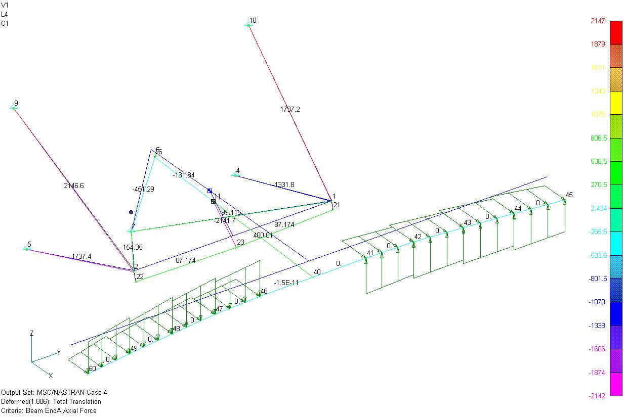
The loads and deflections are shown on Gary's jpg. Many FEA programs
actually show an animation of the vibratory modes with the defelction
exagerated. In this case the deflections are exagerated in the jpg.

Gsmm6gth.jpg

If you don't need that kind of detail a simple graphical analysis
as described below will probably get you into the ball park.

This is on the web site but here it is for my Internet challenged ISP
users :-)

Paul

SUGGESTED FOR BUILDING A ROTARY ENGINE MOTOR MOUNT.

See the drawings on the web site for various motor mount arrangements.

Generic arrangement: There are two welded tri-pods fastened to the
firewall.
Namely BCDE and ADFG. There are another two bipods fastened to the bell
housing bolts with welded end fittings. The welded apexes of the bipods
are
at A and B. The bi-pods are made from small diameter tubing as buckling
would not be a problem due to the short length. Half inch or five eights
should do. The bipods can be optionally braced fore and aft by the oil
pan
and the intake manifold.

As an alternative to the bi-pod mount off the bell housing, a two inch
tube
through the oil pan could be used. In this case no fore and aft bracing
will
be necessary. Make the tube out of 4130 steel 0.050 wall. Where it goes
through the pan it should be jacketed with a larger aluminum tube welded
to
the aluminum pan sides. I don't trust a long aluminum tube in bending
hence
the 4130 steel tube.  Some kind of weird resonent mode could be set up
and
an aluminum tube could fatique right at the welded joint with the pan.
4130
steel has four times the fatique life of any aluminum.

There are two Barry rubber motor mounts at A and B. Similar to the
Questair
Venture mounts. These take thrust, vertical, horzontal and torque loads.
There is a third rubber mount at H which takes thrust loads and some
vertical and horzontal loads. This is located by a welded tripod or
fabricated aluminum box off the fire wall. This mount is subject to very
low
loads. Details of the rubber mounts/joints at A and B are on the web
site in
the built in dyno drawing.

The compact tuned pipe muffler and intake manifold sketches shown in the
motor mount drawings are on the news letter web site. The
motor-mount/oil-sump/heat exchanger is also detailed on the web site.

BENDING MOMENTS, TUBE AND FIREWALL LOADS:

You are dealing with a 1800 ft pound bending  moment and a 1800 pound
shear
load during a six G pull-up maneuver at the firewall. It is assumed the
engine/PSRU/prop weighs 300 pounds and the CG of the assembly is one
foot
from the firewall. A hard landing will also generate these kinds of
loads on
the firewall due to the mass of the engine system.

Some airplane designs, mainly the early Lancairs, had only one foot
between
upper and lower motor mount hard points on the firewall. Consequently
the
1800 pound tensile and compressive loads on the firewall due to the
bending
moment can be halved or only 900 pounds if the distance between the hard
points on the fire wall are two feet instead of only one foot.  The
shear
loads on the firewall will remain the same. This is advantages even if
it
means adding new hard points to the firewall out near the fuselage skin.

It is best to spread the Barry rubber mounts as far apart as possible.
This
minimises deflection in the rubber so softer rubber can be used which
maximises its ability to absorb engine vibration and torque.

It is assumed the cooling radiators are of the Spitfire type, mounted in
a
high pressure area underneath the wings, or, in two hot rod type small
hood
scoops under mid fuselage outboard of the path of the hot exhaust gases.
See
the first web site link on the news letter web site for aerodynamic
details.
A P51 type duct would work best of all but the exhaust pipes should be
off
set to avoid dumping hot air into the inlet.

Only a small oil/air heat exchanger should be required somewhere in the
cowl or other cooling duct to supplement the oil/water heat exchanger
built
into the pan-motor-mount. Also there is room in the cowl for a turbo
charger
intercooler.

HOW TO CALCULATE THE LOADS IN THE MOTOR MOUNT TUBES.

See the tube load drawing on the web site. Make a scale drawing of the
motor
mount. Top view and side view.

Step 1. If the tubes are tilted in when looking down from the top of the
motor mount rotate them so they are parallel with the airplane center
line.
The side view of the motor mount should then reflect the true length of
the
tubes. We are just going to determine the loads in the two critical
tubes
on only one side of the motor mount.

Step 2. Multiply the distance out from the firewall to the rubber mount
times 900 pounds or half the load from the engine during a six G pull
up.
Divide that number by the distance between the upper firewall mount and
the
lower firewall mount. Draw arrows on the side view that are to scale. In
other words if the load is 930 # the arrow should be 9.30 inches long.
Use a
machinist scale marked off in 1/100 of an inch. Notice the bottom tube
pushes in on the fire wall and the upper tube pulls out of the firewall.
Notice also that the firewall pushes and pulls back :-).

Step 3. We will do the bottom tube first. Move the arrow out to the end
of
the tube and draw a right triangle. The length of the diagonal line is
the
compressive load in the tube. In this case it is 974 pounds. Usually
this is
the most critical tube due to a phenomena called buckling. We will talk
about that next. The length of the short vertical line is the vertical
load
on the fire wall where this tube is bolted to. In this case it is 270
pounds for the lower firewall mount.

Step 4. Move the upper arrow out to the end of the upper tube. Draw
another
right triangle. Again the length of the diagonal line is the tensile
load in
the uppper tube. In this case it is 1123 pounds. The length of the
vertical
line is the vertical load on the firwall imparted by this tube. in this
case
630 pounds. Note that 630 pounds and 270 pound equals 900 pounds.

Paul Lamar

CALCULATING THE STRESS IN THE TUBES AND CHECKING FOR BUCKLING.

Written by Bill Freeman:

Once you know the force that the tube will have to support (along its
axis),
you can calculate the stress in the tube (which is the design limit)
from:

         stress = force/area             where the area is the

cross sectional area of the tube.  So calc the area for the outside
diameter
circle

       area = PI * r * r        or  3.1416 * outside radius squared

then subtract the area of the inside diameter circle, same equation, but
use
the inner radius.

You want to keep the tube stress below the yield of normalized 4130
chrome-moly steel which is about 66,000 psi.  I would suggest a 10 G
landing
as the design point for the engine mount.  Paul used six G's above but
you can use ten G's if you want the motor mount to survive a minor
crash.

If the stress is too high, use a thicker wall or larger diameter tube to
increae the area which will reduce the stress.  This is all there is to
it
for a tube in tension.  NOT SO SIMPLE for a tube in compression since it
will possibly fail due to buckling.

Take a plastic soda straw and pull on it as hard as you can with your
two
hands.  Can't break it, can you?  Now push on the ends with your thumbs
-
pretty easy to crumple it up, huh?  This is buckling, which is a lateral
(sideways) instability in a long skinny member under compression.  Long
skinny structural members can fail in buckling WAY below the yield
stress
tensile load.

The simplest thing to do about buckling is to use a relatively large
diameter tube to give a stronger lateral stiffness.  You can go look in
std
eng tables, or if there is enough interest I'll do a short ' how to' on
basic buckling calcs.  But, if you use a realtively large diameter tube
and
decrease the wall thickness to keep the cross sectional area in bounds
i.e.
not too heavy, you will be more buckle resistant.  Also, a center brace,
even with a *very* small brace tube, will dramatically increase the
buckling resistance, because it cuts the effective length of the tube in
half.  Remember, buckling only happens in tubes in compression.

 Bill


Written by Paul:

BTW the bible for this sort of thing is Analysis & Design of Flight
Vehicle
Structures by E.F. Bruhn et. al. Tri State Offset Company 817 Main
Street
Cincinnati Ohio 45202 Published in January 1965.

I am sure Dick Van G keeps a copy along side his drawing table or
computer. I
paid $14.75 for my copy 30 years ago but I'll bet it is well over $100
now.
Well worth it however. Plenty of buckling tables for both 4130 and
aluminum
tubing both round and streamline. See the one on the web site.
bucktube.jpg

There is also a very good chapter on aircraft loads with lots of worked
examples. The book reflects the distillation of 65 years of experience
with
aircraft structures.

STATIC TESTING YOUR MOTOR MOUNT DESIGN.

Static test your motor mount by using the airplane as a jack to pick up
the
front of a front engine car. The average front engine car weighs about
3000
to 3600 pounds so half to two thirds of that is 1500 to 2000 pounds.
Your
static weight target load for the complete motor mount is 1800 pounds.
It is
hard to come up with that much dead weight. You would have to buy 36...
50
pound bags of cement and then find enough room to hang those bags off
your
motor mount so use your car.

Don't worry about the download on the horzontal stablizer. If it won't
take
about 700 pounds down force it won't survive a six G pull out either.
Apply
the force mainly to the stabilizer spar near the point where it
intersects
the fueslage. You can distribute some load along the spar if you need
help.
BTW this in effect is static load testing the entire fueslage and
landing
gear. Don't try to static load test the motor mount to ten G landing
loads.
You will probably fail something in the fuselage or the stabilizer.

Paul Lamar

The Aircraft Rotary Engine Newsletter.              Powered by Linux.

http://home.earthlink.net/~rotaryeng/            http://www.linux.org