Jeff Spitzer wrote:
At 05:15 PM 2/16/99 -0800, you wrote:
A couple of questions. What is the maximum rate of increase in
the duct cross sectional area as a function of the duct length?
A good rule of thumb is to always have your internal area change equivalent
to a conical diffuser with a 6 degree total included angle.  That's 3
degrees per side.  IOW, If you take the cross sectional area of any shape
and convert it to an equivalent circular radius then the rate of change of
radius should be about 3 degrees.
Is this a linear function or some other function? In other words is the
air velocity change linear or accelerated.
For normal diffusers its best to stay linear.  In the unique case of a
diffuser that exhausts into a uniform backpressure element (AKA our heat
exchanger) the rate of diffusion can increase rapidly immediately
preceeding the HX.  The actual rate will be determined by several factors
such as ratio of dynamic head to static pressure drop of the HX, boundary
layer energy, etc.  Also note that in a properly designed system, the HX
face area will often be on the order of ten times the cross sectional area
of the inlet.  It is not practical or necessary to try to have an effective
diffuser for 10:1 area ratio.  In fact, it can't be done.  The attempt to
recover 100% of the theoretical pressure will fail due to excessive
frictional losses on the long duct required.  The answer is: If you have
room then about 3:1 diffusion including external and internal components is
a good compromise.  This slows the air to .33 times it's initial velocity
resulting in a theoretical recovery of 89% of the dynamic head.  Any
internal diffuser that actually acheives 80% recovery is great. A doubling
of duct length would imply slowing the flow to .165 times the initial
velocity and while the theoretical pressure recovery would increase to 97%
(for an area ratio of 6) the actual pressure recovery may be worse than for
the 3:1 diffuser.  So, do as much effective diffusion as you can in the
space (read:length) that you have then dump into a large duct early enough
for the resulting separation to reattach before the HX.  If done right, the
final dump is about one face width upstream of the HX face with swooping
shape using back pressure to avoid any separation at all.  That's a little
tricky to figure without some tools or experience.
Same questions for the exit duct?
The exit duct should be:
-As short as possible because frictional losses add up.
-As large a cross section as possible for the distance that must be traveled
-A rather abrupt rounded edge nozzle at the outlet.  The walls at the
nozzle can approach (or even exceed) 90 degress included as long as the
corners leading into the throat (the final exit) have a radius of greater
than about 1/7 of the width/diameter.

Jeff Spitzer
Thanks Jeff I think this is the core of the design problem.
Getting it to fit in the airplane.

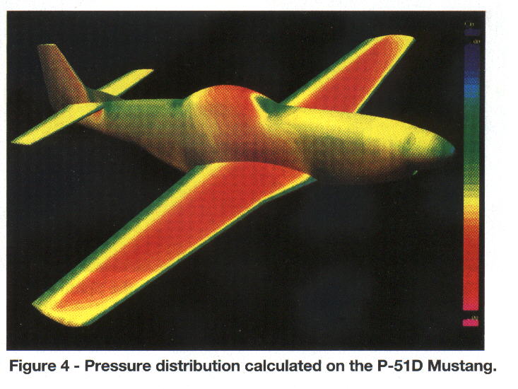
BTW here is a jpg of the P51 pressure distribution from David Lednicers
article in EAA Sport Aviation January 1999.

Notice the low pressure area under the stab on the aft fuselage.
If it were not for the hump on the bottom of the P51 there would
be no low pressure area to dump the rad air in except this one.
Everywhere else on the aft fuselage is moderate to medium high
pressure.

Paul Lamar

The Aircraft Rotary Engine Newsletter.              Powered by Linux.

http://home.earthlink.net/~rotaryeng/            http://www.linux.org