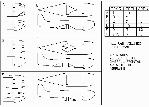
This is a chart to try and asses the efficiency of
different cooling arrangement for low wing airplanes.

The numbers to the right are educated guesses. Jeff
and I more or less agree on these numbers.

If you increase the avg rad volume
beyond about a 650 cubic inches the engine will cool
better but the drag will also be higher.

Conversely if you pick the best cooling arrangement
with the lowest drag and reduce the rad volume the drag
will be lower while the cooling will be worse.

A. Is Jim Mosur's arrangement. IMHO one of the best.
The reason A is better than B is the rads are thinner
and the extreme angle of the rads allows a better
low drag internal diffusion duct. By the time the
air gets to the back of the rad it is going slower
so the right angle turn matters little. This
reasoning also applies to D.

B. Is sort of Ed Anderson's RV6 arrangement with
perpendicular rads. Ed's is really a compromise
between this and Ed Mosur's arrangement.

C. Is a rad entirely in the aft fuselage with a
NACA duct inlet.

D. Is a zig zag rad using 4, one inch thick cores entirely
in the aft fuselage with a NACA duct inlet.
The hot water is fed into the rear vertical header
tanks and is removed from the front vertical header tanks.
This same water feed should be used in system A.
There is also a subtle advantage in this arrangement
over C and E in that the elevator control rod
can pass between the two center rads.
IMHO the best arrangement of all.

E. Is Neil's new arrangement however he has chosen to
increase the rad volume so the cooling will be better
but so too will the drag be higher.
This is more or less the P51 style.
Neil does not have a heck of a lot of choice as there
is little excess room in a Lancair cowl.

F. Is a modified Tracy Crook arrangement for an RV4 with
cheek cowls. It is modified in the sense that the cheek
cowls are opened up at the rear to dump the cooling air
out over the wing in a low pressure area. It would work
even better with longer thinner rads mounted at
an extreme angle.

The efficiency of thick rads can be increased by
using thin rads back to back and feeding the hot water
into the back rads first. For a given rad frontal
area and volume the drag will be the same but the rad
should cool  much better. The numbers in the chart do
not reflect that refinement.

The Power Sport behind-the-engine rad  arrangement is
not shown because the required shorter PSRU's are not
yet readily available.

Paul Lamar          coolcom2.gif

The Aircraft Rotary Engine Newsletter.              Powered by Linux.

http://home.earthlink.net/~rotaryeng/            http://www.linux.org