Jeff Spitzer wrote:
Paul Lamar Wrote
If the inside of the duct looks like this you can't go wrong. I have
already uploaded the coordinates. That's a flap on the back.

use four thin rads back to back with water going into the rear one
first. 15 by 16 by four inches thick. See the sketch I
previously uploaded.

You need of course a boundry layer bypass between the scoop and
the belly.

Paul Lamar          ductgood.jpg
A word of caution:  A long coolant run to an aft mounted cooler followed by
4 passes through small heat exchangers, followed by a long run back to the
nose may add up to too much pressure.  If the pressure drop is too high,
the coolant flow rate will go down which may lead to overheating or local
hot spots.  Maybe a test of the 13B water pump and RX7 system pressure
drops are in order.

Jeff Spitzer
Good advice. If the pressure drop is too high use the zig zag
design. The rads are all in parallel in that scheme. You might
need four barrel valves to adjust the flow in each rad.
A flange and flow restricter would work as well. The temp
in all four rads just beyond the inlet pipes should be roughly
the same.

BTW It amazes me Griffin is building those so-called multi-pass
rads. Those have a couple of bad features. The first is one side of
the rad runs much cooler then the other. Hence the delta
T distribution is way less than optimum. The second thing
is the coolant pressure drop is higher.

Take a look at a late model Toyota rad.
Note how the tubes and header tanks are arranged.
Tubes are oriented in the short vertical direction to minimise
the coolant flow pressure drop and they are all in
parrallel to equalise the delta T as much as possible.

Those Toyota rads are designed right. New header tanks
can be hogged out of 2 X 2 aluminum bar stock on
a mill for the one inch core. Check with a rad shop on
how they go about replacing the header tanks.

I highly recommend letting the air out under the stab.
If a structural bulkhead is in the way (and it is in a
Lancair) move the outlet  holes further forward on the
fuselage skin and use small external ducts along
the sides of the fuselage with small outlet flaps just
under the stabs to take advantage of that low pressure area.

They only need be about six inches high by about three inches
wide to do the trick. The length will depend on where
the bulkhead is. If you form them from 0.050 thick 5052 H32
aluminum and rivit them around the holes they will
reinforce the fuselage  skin in the area of the outlet holes.
Four  or five layers of bi-di carbon fiber would achieve
the same thing.

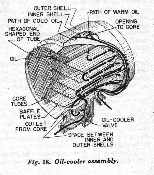
This is going to be a catch all message. Here is a picture of
a WW II heat exchanger. The questions are; what are its
bad features and why are these type heat exchangers not used
anymore?

Paul Lamar                 honeyhex.jpg

The Aircraft Rotary Engine Newsletter.              Powered by Linux.

http://home.earthlink.net/~rotaryeng/            http://www.linux.org