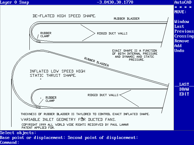
Anybody who wants to make this for their own use is welcome.

I would start with a large truck inner tube.

The idea is: when inflated  the lip radius is much larger
and therefore the low speed thrust generated can be as
high as 50% better than the high speed configuration.

At high speeds the bladder is deflated to reduce the frontal
and wetted surface of the duct to reduce the drag.

To give some idea of how this works if you have a toroid
with a 40 inch diameter hole and an OD of 50 inches
you have a toroid section diameter of five inches.
Therefore  half the surface area of the toroid is
roughly 1110. square inches in
contact with the duct air in-flow.

If the average pressure due to air flowing over this area is .1 psi
above static pressure the additional thrust generated
is approxmately  111 pounds.

If the slip stream air flowing into the duct at full power is 100 MPH
then the dynamic pressure at 100 MPH is 26 pounds per square foot
or 0.188 psi. This situation represents a lift coeff. of
only 0.1/0.188 or 0.53. Even better results may be obtainable.
A wing can generate  lift coeff. of well over one.

An additional thrust of 111 pounds will result in an incremental
initial acceleration of a 1500 gross weight airplane of 0.074 G or
2.37 FPS^2. This could cut the takeoff distance substantially.


Paul Lamar

The Aircraft Rotary Engine Newsletter.              Powered by Linux.

http://home.earthlink.net/~rotaryeng/            http://www.linux.org