Bill Freeman wrote:
Paul,
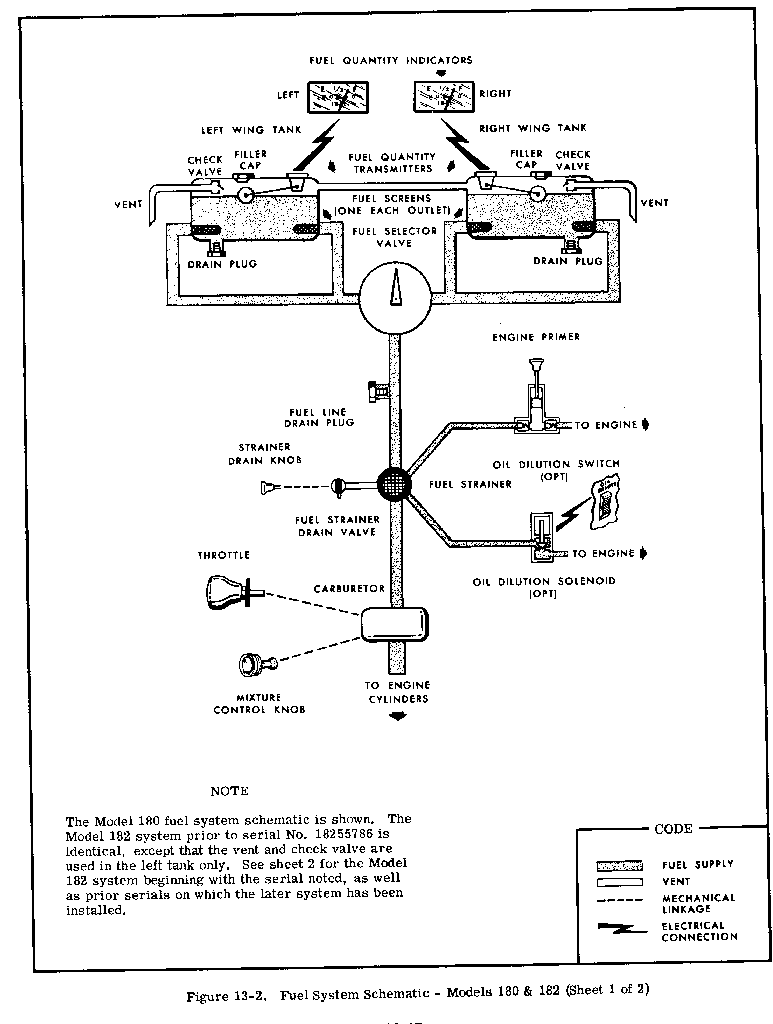
Here are several fuel system diagrams from my Cessna
shop  manual.  Note the single vent comment for early C182s,
like mine. Also note that 182sch2 is the detail of how close they
put the added vent INTO THE FUEL LINE.  Never saw this
before.

 If you are scanning your own images I recommend scanning
them in initially as .bmp (bitmap) files and then scaling to 1280 x
1024 size and converting to a .gif image type.  The .gif will be a
lot smaller for black and white images like this.  Any smaller size
and the type gets lost, but you need to copy it at a high res first
 as a bitmap.  My bitmaps were about 800K but the .gifs were
down to 20K-30K, which send quickly over the net and will
look good on the screen.

Several interesting things can be seen from these fuel system designs.

First, the larger tank systems (C182) have front and rear inboard fuel
pickups.  My guess is that unless you have some sort of a built-in
sump which captures significant quantities of fuel as it sloshes
around when the tank is low (i.e. LARGE inlet, like 2" diam.), you
probably need to have a pair of inlets.  With large fuel lines, you
can get some storage for temporary unporting by just the fuel in
the lines by adding another set of lines with the second pickup,
a slight benefit.
The Aircraft Rotary Engine Newsletter.              Powered by Linux.

http://home.earthlink.net/~rotaryeng/            http://www.linux.org