Paul Yaw wrote:
Paul wrote:
Jeff Spitzer wrote:
At 03:49 PM 6/7/99 -0700, you wrote:
The depth is down to the steel teeth and not to the liner itself.
The steel teeth are there to lock the liner to the aluminum water
jacket.
I am sure the depth varies and depends on who is doing the grinding.
Can someone please post a picture or drawing or both of what this grooving
looks like?

Jeff Spitzer
Hard to see in a picture Jeff. The grooves are about as wide as they
are apart. They are inside the rotor housing on the back face of
the trochoid surface and are perpendicular to the water flow which
of course is front to back on that side of the engine.

Paul Lamar
Down to the steel liner?  The aluminum is nearly a half inch thick.
This mod is normally done with a 3/16" ball end carbide burr.  Is there
someone out there who cuts all the way to the liner?

PY
Its about a half inch at the bump and about .4 inches everywhere else.
The steel liner with teeth is about 0.08 - 0.1 inches thick. That leaves
about 0.3 inches for a max depth slot.

The longest unsupported span in the hot area is about .9 inches on a
late housing
with the knock sensor above the spark plugs. Typical spans are .6
inches.
With some late turbo housings Mazda has gone in with an end mill and
milled
out part of one or more connecting ribs inline with the spark plug
bosses.

My guess is the stiffness of the wall (once the decision is made to slot
in the
first place) will be a modest inverse function of the slot depth.

My contention is making the slots deeper will reduce the rotor housing
shrinkage problem.

Making the wall thinner may increase the heat transfer despite a lower
water velocity as the heat has less distance to travel through the
aluminum.

The slots greatly increase the area of the aluminum in contact with the
water
so the stagnant film thickness resistance to heat transfer is greatly
reduced.
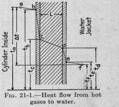
See chart below.

Nobody that I know or heard of has embedded thermocouples in this area
and
actually measured the temperatures. I have asked Jim Mederer this
question
and he said no he did not. I suspect the slots were just a guess.

I have seen oil coking on the trochoid surface but no telling what kind
of
oil caused this. To reduce this coking was probably the reason the slots
were tried in the first place. As I recall Everett mentioned this.
We used to sit around and discuss these kinds of issues for hours on end
at airshows and at his place.

With different apex seal lube oil, such as two cycle oil, slots may not
be necessary and the efficiency of the engine improved by letting the
walls of the combustion chamber run somewhat hotter.

Another limit on how hot you can run it is the rotor housing shrinkage
problem. Smaller diameter, high stress tension bolts would help here.
Another trick is to place belleville washer  springs under the nuts
on the tension bolts. These types of tricks need to be carefully
calculated as you don't want the housing springing apart under
combustion pressures or the tension bolts failing.

The ideal configuration (not possible with the Mazda design) would be
to bolt the housing together with flanges like turbojets are
constructed.

Be all that as it may I am sure Mazda has FEA modeled this area for heat
transfer by now but probable for typical car average HP levels.

A very interesting SAE paper on this subject for aircraft piston engine
cylinder heads is:

* SAE Paper # 871042    0148-7191/87/0428-1042 $12.50 Design and
Development of the Voyager 200/300 Liquid Cooled Aircraft Engine by
R.E. Wilkinson. Twenty pages. Published in 1987. This paper is about
the engine used in the Rutan Voyager around-the-world un-refueled
record holder.

Where-in Continental actually embedded a bunch of thermocuples in the
head material around the combustion chamber and attempted to run the
metal as hot as possible to improve efficiency.

Here is a chart and interesting quote from Taylor's books. heattx.jpg

"Heat Transfer.    -Of the three means of heat transfer,
conduction, convection, and radiation, in cooling engine cylinders,
conduction plays an important part in carrying the heat through the
thin layers of stagnant gas and water in contact with the walls. The
rest of the heat exchange is done partly by radiation but chiefly
by convection. The heat flow' from one fluid to another, separated
by a metal wall, can be best explained using the diagram in Fig.
21-1. The temperature ta of the gas at point a in the interior of
the cylinder gradually falls to the value tb at the surface of the
inert gas film. The resistance of this film is very great, a great
temperature head, tb - tc, being required to pass through it by
conduction. The temperature head required to cause the flow through
the metal wall is tC - td.  The temperature head required to pass
through the outside film is td - te.  Its value is comparatively
small if the cooling fluid is water and large if it is air.
Finally, the temperature drops to tf of the cooling liquid at some
distance away from the wall."

Nucleate boiling probably takes place in d to e.

Paul Lamar

The Aircraft Rotary Engine Newsletter.              Powered by Linux.

http://home.earthlink.net/~rotaryeng/            http://www.linux.org