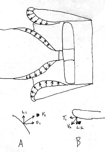
This is a vertical section through Perry Micks ducted fan
on the back of his EZ.

It is a good example of why one cannot consider just the mass
flow through the fan when estimating the thrust.
The large radius lip on Perry's duct generates a thrust
on its own from the air flowing over the large curved
surface. If you add up all the little T1 components
of the pressure vector V2 you will get the thrust
from this pressure distribution. One can verify this, as I have, by
holding your hand on the outside of the duct and noticeing
a forward airflow around and into the duct.

Unfortunately this effect is partially
canceled in Perry's application by the large hump in the
cowling to enclose the stock intake manifold. I will have
some pictures of this later today. As you can see in sketch
A the drag component of vector V1 added up will partially cancel
the thrust components of vector V2.

At high speeds however the large lip becomes a liabilty
as dynamic pressure over comes this effect and the direction
of the pressure vectors is reversed and the drag components
become dominate. However the cowling pressure situation is more or
less the same and the vector V1 does not change direction so
these drag components merely continue to add drag to the
airplane.

This is why I state Perry Micks duct is a low speed duct
and why one cannot ignore the drag of the duct when
calculating the thrust. One must take into consideration
the added drag of the duct when estimating the thrust at
high speeds.  In the extreme if you add x amount of
thrust to a small diameter prop by enclosing it in a duct
and you also add x amount of drag. You have achieved nothing.
You are still stuck with the low efficiency of the small
diameter prop. Further more you are also stuck with the
excess weight of the duct.

However at low speeds this kind of duct may show advantages.

Paul Lamar

The Aircraft Rotary Engine Newsletter.              Powered by Linux.

http://home.earthlink.net/~rotaryeng/            http://www.linux.org