F. Marc de Piolenc wrote:
Paul wrote:
Jeff Spitzer wrote:
I designed several ducted fan propulsion systems while at Moller.
Hmmm...
The efficiency of a ducted fan is HIGHLY
dependent on uniform inflow.
Experiment shows lightly loaded fans (the right kind for good
propulsive efficiency) are highly INsensitive to both radial and
tangential non-uniformities. One of my main reasons for pursuing these
things.
You will not obtain uniform inflow with your
small hub radius and large bumps. Every ducted fan designer faces the same
problem.  The best compromise is to use a large ratio hub.  I'm not up to
speed on the aero of the fan but I believe there is actually a "best" point
at around 50%-60% hub to tip radius.
So long as the blade-angle distribution of the blade is correct for the
conditions, hub radius matters little. At about rhub = .20 R it becomes
almost impossible to meet that condition and the blade root bending
moment turns the blade into a club, but this is a structural, not an
aerodynamic problem.
If you mean you must increase the thickness to sustain the stress
it is also an aerodynamic problem. PL
If you do this to your package you
will have to use more blades in order to get the proper CL.  Typical ducted
fans have many blades for this reason.  A number like 8 might be about
right.  Another advantage of more blades is cascade efficiencies.
Cascade EFFICIENCIES?! Operating in a cascade REDUCES a blade's
effective turning angle. The only reason for high-solidity fans is that
the design is so screwed up in other respects (typically too highly
loaded) that there is no other choice.
I would not call a high bypass turbo fan design "screwed up"
It sure gets you there on an airliner :-) We are talking 6500 RPM
here. That means the fan is highly loaded compared to a prop
because the tip speed is limited and therefor so too is the diameter
and the fan area. Hence high fan loading. To make this work you must
start with a fan RPM of 6500 RPM or you will not have the HP you need
out of a rotary engine. PL
A well-designed propulsive fan
will usually end up with a low enough solidity to be designed by the
"isolated airfoil" method.
Perhaps but you may need a gear box to slow the fan. If that is the case
then you have defeated the reason for the ducted fan in the first place.
Namely to eliminate the weight and expense of the gear box. PL
More
blades allow you to run higher pressure ratios further improving the
efficiency of your duct.
Higher pressure ratios result in higher velocity ratios, resulting in
LOWER propulsive efficiency.
Absolutely and this is the reason it does not work in the speed range
of most experimental airplanes. PL
Note, BTW, that I'm not suggesting lower mass
flow.
If you hold power constant, higher pressure ratios WILL result in lower
mass flow - no way to avoid that as total p, v work has to remain the
same.

Folks, this is why George and I wrote the book. I'm beginning to
understand why Moller has been promising results for so many years and
not delivering anything but brochures.

Marc de Piolenc
Our man Jeff Spitzer here is no dummie.

Jeff & Dr. Paul Moller knows it takes gobs of excess HP to get a ducted
fan design off the ground. Just like an airliner. He provides that with
eight
120 HP rotary engines.  He also targets  the top speed at 390 MPH which
is in the high efficiency range of the ducted fan. There is nothing
wrong
with Moller's design. The problems are political and economic. Imagine
what your neigbors would say with eight screaming rotary engines
generating
960 HP taking off in your driveway or the ATC problems with SkyCars
flitting
around all over the place at 390 MPH and 30,000 feet :-).

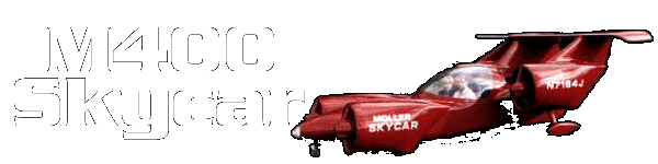
http://www.moller.com/skycar/m400/

Moller-skycarM400.gif

Paul Lamar

The Aircraft Rotary Engine Newsletter.              Powered by Linux.

http://home.earthlink.net/~rotaryeng/            http://www.linux.org