ingenuir@ix.netcom.com wrote:
On 09/02/99 21:56:36 you wrote:
I was not always entirely happy with the three inch square aluminum
tube motor mount. Then I started thinking about how I could
optimise the space under the engine to allow installing a large area
thinner radiator for good cooling. I then realized that if I went to
a truss design the lower member of the truss would always be in
tension.
  Whoa, Paul! Engine mount trusses for both tractors & pushers react
vertical loads similarly: The lower strut pushes (compression) the
engine up while the upper strut pulls it up.
Wrong truss. You are talking about the longitudinal trusses.
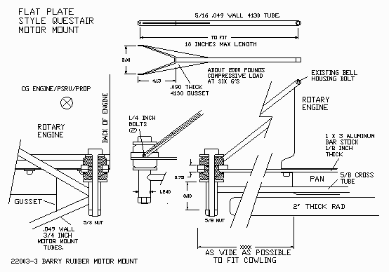
  I think you are talking about building a pair of transverse trusses
from the center of the RHS & LHS rubber motor mounts on your aft (in
a pusher) tripod-bipod hard points to the top and bottom of the aft
(propeller) end of the engine. (See flatpanm.gif)
Yes, Now you have it.
So I decide to go with a one 1/8 inch by three inches wide
flat aluminum bar stock. This would allow using the pan bolts to
bolt it to the bottom of the engine near the rear end housing
area. (The front of the engine in a tractor installation.)
It would also allow raising the motor mounts relative to the
engine as well.
  You really do need to do 3-D drawings of this stuff (or at least
identify views) to be sure all the struts clear engine parts and that
the struts provide all the required reactions. I see four questions
off the top:
I would love to do three D. Got a copy of Solid Works laying
around you are not using?
1) Did I guess right about your design concept?
Yes.
2) How are you transfering engine thrust loads to the mounts?
Through bending of the flat plates in the horzontal plane
and tension load in the third mount not shown in flatpanm.gif.
Thrust loads are minor compared to the six G pull up loads.
I have decide however to change the flat plates to shallow
channels for vibration reasons.
3) How much bending stress will be in the welded truss joint?
Don't really know. I have not looked into it yet. You are
talking about the gussets on the 5/16 dia 4130 tube are you
not?
4) How much bending stresses are in the 0.049 x 0.75 in. motor mount
tubes due to the downward offset from the rubber mounts?
What downward off set from the rubber mounts? They intersect the
center of the rubber mounts. There should be no bending loads
in those 5/16 tubes other than what is in the forked part.
There are no major bending loads in the flat plates either
other than the 1/4 inch or so offset of the 1/4 inch bolts.
The compressive load in the top member of the truss
is about 2000 pounds which will not buckle a 5/16 diameter
0.049 wall  4130 tube eighteen inches long. The tubes
are attached at the top to existing bell housing bolts.
  No comment on loads or allowables at this time. Don't forget torque
and thrust also add +/- loads. When you get the design sorted out, we
may work out a FEM of it to get scaleable strut and joint loads. I
just found an old posting about Vince's motor mount that I'll try to
comment on this weekend.

Gary Moir, PE, NASTRAN / FEMAP finite element analysis
GAMA Ingenuirity
ingenuir@ix.netcom.com
The Aircraft Rotary Engine Newsletter.              Powered by Linux.

http://home.earthlink.net/~rotaryeng/            http://www.linux.org