I have been giving a lot of thought lately to the cooling
problem. So far we have been going on pure experiment only.
I thought I would run this by you for comments.

Preliminary givens:

A: The cooling HP  needs of the engine is fixed at roughly 100% of
the output HP and not a function of airspeed. Particularly
with a constant speed prop. One HP is 2545 BTU's per hour
or 745 watts. Normally aspirated output HP of course decreases
with altitude.

B: The mass flow of air available for cooling with
a fixed air inlet area is directly proportional to air speed
and air density. It is proportional to air speed times inlet
area times air density. The worst case is probably climb
air speed or about 80 to 100 MPH.

C: Given a perfect duct or 100% dynamic pressure recovery,
the mass flow of air passing through a radiator is proportional
to dynamic pressure which is proportional to the square of
speed and inversely proportional to the thickness
of the radiator.

D: The temperature increase of the cooling air exiting
the radiator is directly proportional to the square
root of the thickness of the radiator.

E: The first half of the radiator does 3/4 of the cooling.

F: The cooling heat lost to the air is proportional
to the product of the mass flow of air times the
temperature. The neccessary heat loss or cooling HP
is fixed. See A:

G: The automotive companies have optimally portioned (thickness
and area) radiators for climbing hills at 65 MPH. Therefor
these proportions are close to our needs.

       DYNAMIC PRESSURE
 Air
Speed
 MPH    PSI    Inches of H2O
  60   0.065      1.80
  65   0.076      2.11
  70   0.088      2.44
  75   0.102      2.81
  80   0.116      3.19
  85   0.130      3.60
  90   0.146      4.04
  95   0.163      4.50
 100   0.181      4.99
 105   0.199      5.50
 110   0.218      6.04
 115   0.239      6.60
 120   0.260      7.18
 125   0.282      7.79
 130   0.305      8.43
 135   0.329      9.09
 140   0.354      9.78
 145   0.380     10.49
 150   0.406     11.22
 155   0.434     11.98
 160   0.462     12.77
 165   0.492     13.58
 170   0.522     14.41
 175   0.553     15.27
 180   0.585     16.16
 185   0.618     17.07
 190   0.652     18.01
 195   0.687     18.97
 200   0.722     19.95

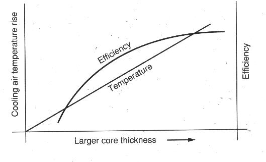
The chart below is from Corky Bell's book Maximum Boost.
Obviously it is for only one dynamic pressure,
air density and inlet area. The max efficiency
point as a function of rad thickness and inlet area
probably varies with dynamic pressure.

G: The automotive companies have optimally portioned (thickness
and area) radiators for climbing hills at 65 MPH.

radeff.jpg

Paul Lamar

The Aircraft Rotary Engine Newsletter.              Powered by Linux.

http://home.earthlink.net/~rotaryeng/            http://www.linux.org