This is from a paper that Juergen Bax gave me on radiators.
It was used to publish SAE 920549.

Unfortunately it was not  done in absolutes terms so
it is a little hard to extrapolate to aircraft requirements.
Everything is relative to a mythical copper double row
radiator. The paper was done by Honda and Showa Aluminum Corp.
This is typical of modern SAE papers as the car manufacturers
do not want to hand out too much factual information.

Never the less we can learn a lot from it about rads.
The numbers refer to how well the new one row rad design did
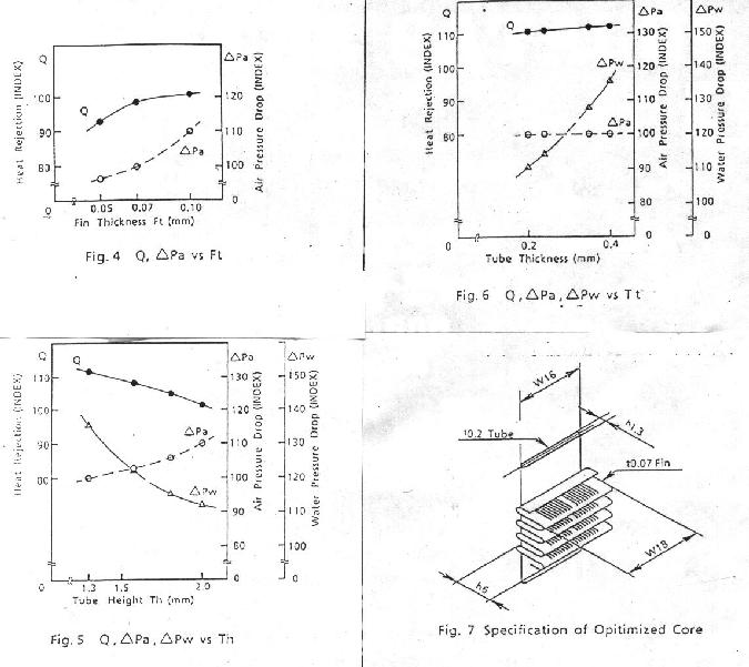
relative to the copper two row design. In figure 4 is shown
aero pressure drop (delta Pa) verses heat transfer (Q) verses
fin thickness verses water pressure drop (delta Pw).

Aero pressure drop is important to car manufacturers for
the same reason it is important to us. Less pressure drop
means lower aerodynamic cooling drag. From Fig 4 a fin
thickness of 0.07 mm was chosen.

Fig 5 shows all three parameters. Water pressure drop
(delta Pw), Aero pressure drop and heat rejection.
Heat rejection is the bottom line. Temperature
difference between inlet air and outlet air says little
about heat rejection. That must be related to the mass
air flow as well as temperature difference.

A low water pressure drop is good because it requires a
smaller water pump for a given flow. Serpentine radiators
as sold by car racing outfits are not good. It is best to have
all the tubes in parallel as that reduces the water
pressure drop.

Fig 6 shows everything as a function of tube thickness.
Honda was looking for less water pressure drop to reduce
the HP consumption of the water pump so
the tube thickness was chosen at 0.2 mm. Note that
the aero pressure drop was constant and the heat rejection
varied very little with tube thickness.

Fig 7 is what Honda came up with. This rad had about half
the water volume as the orginal copper rad and the empty
weight and full weight was also about half of the copper rad.
The thickness of the rad is half of the orginal copper
comparison rad "standard".

The fins were extended out beyond the thin wall tubes to
protect them.

In so-called "middle speed" driving and "high speed" driving
the heat rejection was more or less constant. This is to
be expected as the mass airflow and the rejected HP
heat both increase with speed. It is important to get
the rad to work for climb and high speed cruise will take
care of itself. Juergen Bax told me the test standard
for automotive radiators was an airflow through the rad
of only three meters per second or about ten feet per second.

This low airflow speed can be achieved in aircraft by using
a properly designed internal diffuser duct. An
oblique block or highly angled, large area, thin
radiator  design such as shown on the ACRE NL site
obviously works very well for our applications.

The brute force approach of jamming a lot of air through
a thick, stright up rad will cool fine at the expense
of high aerodynamic drag.

I am sure everybody has questions so have at it. I will
do the best I can to answer them based on what I have learned
so far. This is just the tip of the rad research iceberg.

Paul Lamar

The Aircraft Rotary Engine Newsletter.              Powered by Linux.

http://home.earthlink.net/~rotaryeng/            http://www.linux.org