Fred wrote:
I did some analysis for Marv Kaye's rotary in Lancair project using the data
and procedures in Compact Heat Exchangers.  I focussed on a fin design
available from TEMP, a manufacturer of aerospace heat exchangers, and one
which has close to the best heat transfer per horsepower (to move air)
performance.  This is equivalent to lowest drag per unit of heat transfer.
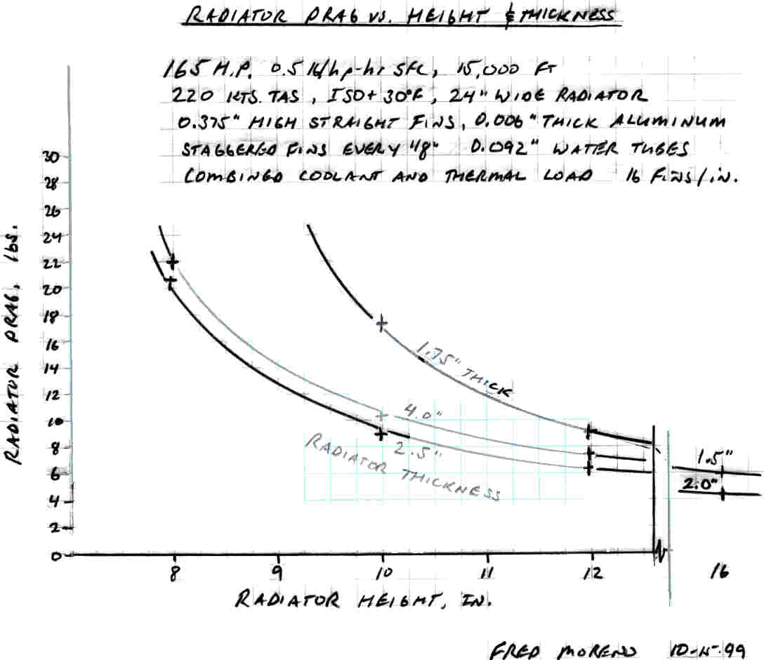
The results of numerous computer runs are shown in the hand drawn plot
attached.  Some explanation may be helpful.

The fin configuration chosen is 18 fins per inch, .375 fin height (distance
between tubes), straight fins, staggered every 1/8 inch.  Tubes are about 0.1
inch thick (similar to the usual 0.1 by 1.0 inch tubes found in auto
radiators).

Drag is the momentum drag (cooling drag) that results from the cooling air
flow alone assuming that the outlet area is adjusted via cowl flap to the
optimal value to accelerate the existing hot air as much as possible using
any surplus pressure left over after paying the losses in the inlet diffuser
and across the radiator. No drag effects from external belly scoops, etc. are
included since they require separate analysis.

Radiator width is held constant at 24 inches.  (Width and height are
interchangeable - it's the frontal area that counts).

The analysis assumes that the enough air is forced through the radiator to
carry away the heat which must be rejected.  Thus if the radiator is too
small (as in too thin, not enough surface area) more air must be forced
through it to get rid of the heat.  Higher drag results.

Altitude is 15,000 feet, and power is 165 HP, 75% of the 220 hp that Marv
gave me to work with (turbo engine).  As I recall, the BSFC assumed is 0.5
lbs/hp hour.  Lower altitudes can get by with smaller radiators due to higher
air density.

Interpretation of results:

More radiator frontal area equals less drag.  No surprise.  The problem is
packaging a big thin radiator in a little airplane.  Two radiators in a
shallow V might be possible to conform to the round cowl shape.  I favor the
chin scoop previously illustrated (Beckman air plane? - I don't recall) with
radiators below the engine blowing their exhaust upward to cool the hardware
in the cowl before exiting out the bottom by the firewall or out the side.
Use cowl flaps.

For a given frontal area, you can make the radiator too thin (does not heat
the air enough and so lots of air flow needed) or too thick (too much
friction loss for amount of heat transferred).

There is an optimal thickness for each frontal area.  It is thinner as the
radiator frontal area gets larger.

The larger the frontal area, the less sensitive the drag is to radiator
thickness.  In other words, larger radiators are more forgiving if the design
is a bit off optimum.

All this seems to pass the "smell test" - makes some intuitive sense if you
think about it long enough.

>From this, some very rough rules of thumb can be deduced.

Make the radiator about 2 to 2.5 inches thick.  A bit thinner if you go
slower (since there is less ram pressure) in which case you will need a bit
more frontal area.

Looks like low drag requires 12 by 24 or 16 by 24 inches of frontal area for
165 horsepower, or 1.75 to 2.3 square inches per horsepower.  Going faster
permits smaller frontal areas because ram pressure is greater.  For
reference, for a liquid cooled 375 HP Lancair IV at 320 knots and 25,000
feet, the radiator selected is 2.5 inches thick and has about 1.2 square
inches per horsepower, but assumes a bit lower SFC (lower heat rejection) of
about 0.4.  It uses the same fin configuration.

You will probably need cowl flaps opened to create more area and a bit of
suction in any case to cool adequately on the ground or in hot, slow climb.

Be aware that the NASCAR radiator designs using lots of little louvers on the
fins (like I saw on the Atkins' plane at Golden State fly in) have much
higher drag per unit of heat transfer and are to be avoided if you want an
optimal design.

Hope this helps.

Fred Moreno
Thanks for sharing this with us Fred. This is the first usefull info
I have seen for our needs. Will TEMP sell cores at a reasonably
price?

This is the first of two charts Fred sent. Fred-Moreno-radiator1.jpg
The second will follow.

Paul Lamar

The Aircraft Rotary Engine Newsletter.              Powered by Linux.

http://home.earthlink.net/~rotaryeng/            http://www.linux.org