Bill Freeman wrote:
Here are some allowable tension loads for a few sizes of 4130
steel tube, with the limit defined by onset of permanent deformation,
not actual fracture.  Fracture is at least 50% higher, except in
buckling which is highly nonlinear.  If you have a 350 lb motor,
design for 3500 lbs in the downward direction, i.e. a 10G "uh-oh"
 landing, and you'll hve PLENTY of margin.

        TUBE            lb/ft       max tensile load, lb
    1/2" x 0.035"    0.1738             3066
    1/2" x 0.049"    0.2360             4162
    5/8" x 0.035"    0.2205             3892
    5/8" x 0.049"    0.3014             5320
    3/4" x 0.035"    0.2673             4717
    3/4" x 0.049"    0.3668             6475

Bill
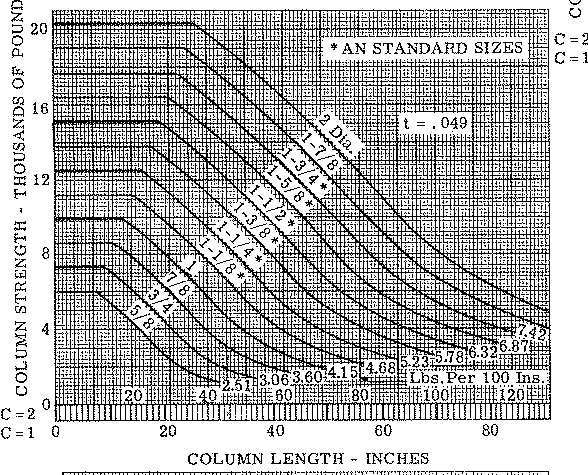
Bill I have a buckling chart on the ACRE NL web site from
the bible of aircraft design; "Analysis & Design of
Flight Vehicle Structures" by E.F. Bruhn.
None of the loads on motor mount tubes get anywhere near
these numbers. Buckling and bending mode vibration are the main
criteria for tube size.
Agreed, if your total load is ~3500 lbs (10G) then a multi tube mount
made up of materials where a *single* tube is acceptable to take a load
of 4000-6000 lbs in tension, with a 50% margin to failure should
be OK (DUH!).    I didn't bother to look up the buckling loads, since
they are so length dependent.   When buckling is an issue, either go one
size larger or add a brace as req'd to reduce the effective length.
Your table is great, but I can't find it - what is the file name?  All my
stuff is a work.  I'd first lay out the mount in
5/8" 0.035 and then got up or down in size as seems reasonable,
once the lengths are established.  Basically, buckling is checked
after the first run through, once the compressive members are
located and their length is determined.
This is an early RV4 motor mount drawing. Since this was drawn I
recommend
using a shallow 4130 steel hat section instead of the two inch
diameter tube and moving it toward the firewall about three inches
under the front rotor housing. Also the diagonal brace tube is not
shown.
With the hat section the rubber mounts are also raised a couple of
inches. I guess I need to redo this drawing showing the Van's landing
gear socket tubes. If Mike can wait a couple of days I will do
that. The next projects are pay monthly bills and do the remote
anemometers
as I recieved the hall effect sensors from Digi Key today.

Paul Lamar
Do you think a trunkaed version of this mount could mate with the stock
Lyc mtg pts and actually do in 4130 tube (and hat) what Mike wanted
to do in alum plate?  You've spent a lot more time than I on this issue
of fitting all the stuff into the cowling - since I don't need to actually do
this, I've sort of let those posts slide by and don't have a good feel for
whether this is possible or not.  Seems pretty tight, but perhaps possible.

Bill
It would be tough as the dimensions of the rubber mounting points are
so close together. It is easier to cut all that crap off there
and weld up near the widely spread firewall hard points. One needs to
make a ridgid welding fixture to hold everything in alingment however.
See the drawing on the web site of such a fixture made from
hardware store perforated angle iron. I have a picture too but I have
not
got it on the web site yet.

Here is the buckling chart. It is on the web site under motor mounts.

Hey everybody please take the time to look at all the pictures
on the web site.

Paul Lamar

The Aircraft Rotary Engine Newsletter.              Powered by Linux.

http://home.earthlink.net/~rotaryeng/            http://www.linux.org