Jim Mantyla wrote:
Hello Paul,

I just had a chance now to review my messages and have had a chance to think
about what you suggested.

My experience with the Mazda engine is not very current as the last one I
saw was 12-13yrs ago.As I recall it was kind of heavy,very noisy , ran hot
and used a lot of gas.This particular setup ,I think was made by an outfit
called "Duncan".

I am concerned with fitting a taper to the end of the shaft for a couple of
reasons,
1)the design as you have shown is virtually identical to the shaft on the de
Havilland "Chipmunk",which has a history of prop departures.This is more
common on the metal prop vesions.(hence the AD on the tapered shaft
models.)We have a member of our RAA Chapter with the oldest Chipmunk in
existence.(serial #006 and he is now rebuilding due to losing his wood prop)
All of the failures occured at the keyways.
2)The advantage of the taper is that it does ensure exact concentricity, but
this can also be acheived with a size for size fit as I have designed the
drive.
3)The taper fit is difficult to machine and is beyond most hobby
machinists.To machine the keyways in a tapered bore is definitely a tricky
thing to do.My design has well supported keys and only subjects the keys to
torsional loads and more importantly the keyway regions have no flexural
loads imposed on them as a tapered shaft system would.For most homebuilders
we can't just say damn the cost we have to be somewhat practical in our
design approach.(I don't dare pass the collection pot around at a chapter
meeeting, if there's buttons on the upholstery) The output shaft on any
reduction drive, regardless of being belt drive or gear drive is esentially
the same.I haven't seem any tapered shafts yet.I have seen a lot with a
couple of bolts going through both the shaft and the prop hub to secure the
hub to the shaft.My system is definitely better than this!

You mentioned that the threads inside the output shaft could cause the shaft
to fail.On your suggested fix, you had a 1" hole bored from the other end to
virtually the same point.Let me address this.
1) Superior shafting is not known as a "notch sensitive" material.
2) The diameter of the shaft at this point is substantial and will almost be
filled up with the grade 8 bolt.
3)the 1" hole will make things difficult because when the shaft is welded to
the back of the ring gear it will cause the air inside to expand and push
the water out of the inside of the ring gear/shaft assembly.(the shaft is
welded on while sitting in an aluminum pie plate with water in it, to ensure
the gear doesn't lose it's temper dueing welding)
4)Holes more than  4X their diameter are difficult to bore.Drilled holes
tend to wander  and could result in an imbalance of the shaft.

The bearings which support the outputshaft are very similar to the wheel
bearing of a front wheel drive car, only bigger.These bearing , with oil
lubrication have a tremendous load rating and to date with my application
have given no problems.In addition to the support from the bearing there is
support from the 3 planet gears which exert a self centering influence to
the output shaft/ring gear assembly.

Paul, I don't want this to get into a pissing contest between you and I (it
hasn't yet, I hope).The drive was designed for the EA-81 engine and it seems
to meet my original design criterion very well.I don't know very much about
the Mazda engine but I would like to know more.
I welcome any suggestions with an open mind and hope that if there are
improvements to be made people will speak up and let me know.

On anothe note, now can I join the mazda group?Is it similar to the Airsoob
group?

Jim Mantyla
OK Jim you are permanently on the list.

So don't bore the one inch hole in the shaft it will only save about a pound
anyway.

Several people have mentioned that tapers are no problem at all to machine
when done on an NC lathe. This is a critical part. Saving $300 to $500 is
stupid when it comes to something like this. The loss of the prop could
put the CG out of range and make it difficult to fly or crash land the
airplane.

Don't take my word for the inadequacy of the shaft but hire an aircraft stress
analyst to do a check on the shaft.

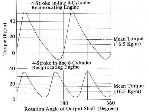
Remember that four cylinder engines are actually worse than the Mazda when it come to
torque pulse.  The peak torque pulse can be four times the average torque. See the
enclosed chart.

Have the stress analyst also look at the prop gyro loads when undergoing a
pitch rate of at least one radian per second.

Typical aircraft  PSRU shafts are 1-7/8 to 2-1/4 inches in diameter for very good
reasons. The fact that a bolt is in that 5/8 hole does not help.  In my opinion
even if your 1-1/4 inch diameter  shaft was solid it would still be inadequate to
survive for very long. The strength of the shaft is proportional to the cube of the
radius so a 1-7/8 shaft is roughly three and a half times stronger than a solid
1-1/4 inch shaft.

In the mean time, until changes are made, I stand by not recommending this design.

Paul Lamar

The Aircraft Rotary Engine Newsletter.              Powered by Linux.

http://home.earthlink.net/~rotaryeng/            http://www.linux.org