Paul Lamar wrote:
Steel is three times stiffer than aluminum and twice as stiff as cast iron.
Would internal pressures dynamically warp, or "oil can", the steel with an
open  sided, cast aluminum side housing ?
You are not going to oil can a crescent shaped  piece of 1/8 thick steel
three inches wide at it widest point and six inches long with combustion
pressure. Besides that it is supported by the required water jacket
baffles.
Paul Lamar
grobbins wrote:
I'm talking about the whole housing, across it's roughly 8"x12" oval bolt pattern, with
a 2-1/2" hole in the middle. I don't think that 1/8" steel plate is anywhere near as
stiff, across the bolt pattern, as the 1-1/2" thick original 1pc hollow casting.
That is kind of not relevant isn't it? We are talking a sandwich here. It is
bolted to a rotor housing. The three inch thick rotor housing is very stiff
in bending.
I'll
bet I can place a similar shaped piece of 1/8" steel, support it at the outer edge, and
"oil can" the center with hand pressure.
Give me a number. How far do you think you can bend it with hand pressure?
How much hand pressure?

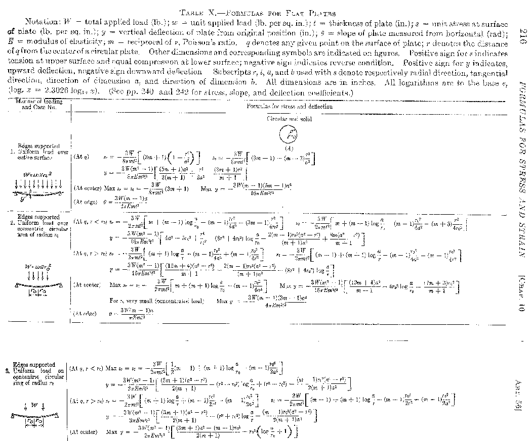
The page below is from Roark. Care to make the calculations or should I do
it? :-)

This is not relevant to what we are talking about here. If you take this
same piece of steel and bolt stiff collars, two inches wide and three inches high
all around the  out side edge on both sides of the steel plate the situation will
change drastically.
The configuration of the aluminum backing the
steel up isn't much better.
Why not?
At WOT with a turbo, combustion pressure across the combustion portion's limited area
would add up to significant total pressure, at least in the combustion area.
Yes, perhaps 800 PSI as I recall and that is when the exposed side wall is of
minimum area. Perhaps less than a half inch wide. As the chamber gets bigger
the pressure rapidly drops off. The load on the rotor face is way higher
than the load on the end housings.
 Neither
the flat steel or the aluminum structure backing it up have thru bolts at the center.
The steel is backed up with a likely weaker, fatigue wise, single wall aluminum
structure. I see little beam stiffness across the center added by the short or curving
internal aluminum baffles, as they are attached only to the aluminum, and they are being
bent the "easy" way as the unattached edges of the baffles are in compression.
Any lateral movement at the center of the end housing also effects the side seal's
efficiency, and they will also see more blowby heat.
You are forgetting the stiffening effects of the steel phasing gear and main
bearing holder. There will be very little lateral movement at the center of
the housing for the reasons I stated above. Look at the structure as
a beam with the aluminum wall in tension and the steel plate in compression.
The only thing missing is the shear connection between the aluminum
baffle columns and the steel plate. This shear connection is provide
by the tension bolts and the bolts holding the main bearing/phasing gear
device. This shear connection could also be provided by flat head
screws threaded into the water jacket baffles. IMHO they would
not be necessary.
Seems rigidity would be a pretty important criteria for end housings.
I do not agree it is as important as you think it is. PL
If you still think the 2pc design is good, you just might have the determination
to make it work.
Grant
The Aircraft Rotary Engine Newsletter.              Powered by Linux.

http://home.earthlink.net/~rotaryeng/            http://www.linux.org