VO wrote:
Paul,
I did in DXF compatible software and probably DXF file will be
suitable. What kind of process are you using? CNC? or Laser?
What associate cost could be? Should I find local shop, any
hints on that in NC, RTP area?
I am not sure about that yet. A DXF would be fine but keep it simple.
No layers. If I cannot load it into ACAD 11 you can send it as a gif or
in the worst case a bmp and I can convert that to a gif. PL
I could make practically any picture format is currently in use most.
Let me know which one are you need.
Send me both a DXF and a gif.
What kind of process are you using? CNC? or Laser?
What associate cost could be?
Should I find local shop, any hints on that in NC, RTP area?
Hydro Jet. High pressure water with an abrasive. Cheaper than NC
milling.
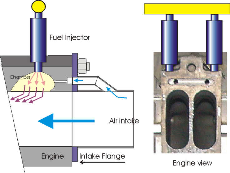
this part could be simplify? Perhaps it good idea drill small
holes in top of intake holes to make some air stream to the
injectors chambers? Suggestions?
Well if you don't mind the extra complexity it is worth a try to improve
the fuel burn. Is it high pressure air that is injected? If so where does
that come from? If a pump is used the pump will absorb HP of course.

Jon, got any idea what Mazda is doing with those small holes
over the intake ports on this engine. Some sort of smog function perhaps? PL
That small holes goes in to Fuel Injector chamber. So it is air intake for
that chambers. Look on the picture which is self explanatory.

Vlad
N1UT
OK I see how that works. It works because of the turbo charger
and the high pressure air in the intake manifold.
Are you going to turbo charge your three rotor?

Paul Lamar

The Aircraft Rotary Engine Newsletter.              Powered by Linux.

http://home.earthlink.net/~rotaryeng/            http://www.linux.org