Hi Paul,
The following comments:

FERRULE
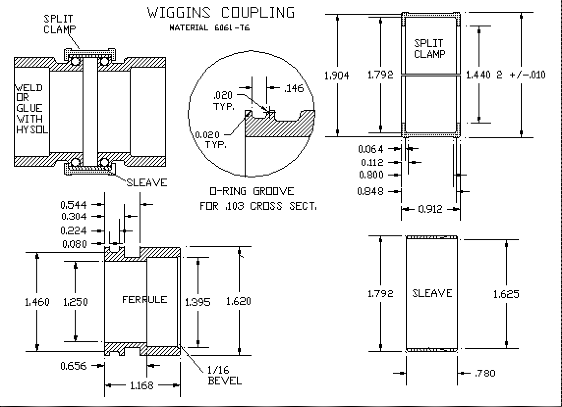
-Undercut dia. next to 0-ring groove, is that dia. also
1.395?
Yes. Probably saves a bit of programming and simplifies the drawing
a tiny bit.
-I would turn the ferrule O.D. to 1.615 dia. throughout
and remove the 1.600, this way you cut down the
clearance between the sleeve 1.625 I.D. from .0125
to .005.  You really don't want too much play there you
could loose O-ring squeeze due to possible vibration at
the joint.
Yes I think I did that on the very last drawing.
-Move the O-ring groove corner radius arrow away from
the hatching, it may be missed and it's an important
radius.
OK good point.
-Instead of giving an O-ring groove depth dimension
of .080, give a dia. ie: 1.440.  The reason is that of
manufacturing tolerances, ie: if the tolerance is + or -
.002 by specification, the groove depth dimension of .080
will be sloppier than that of the 1.440 dia., resulting
in lost of O-ring squeeze.
OK another good point.
-The counter-bored 1.395 dimension should have a bevel
at the entrance for two reasons, 1st to facilitate entry
of the tubing, 2nd to allow for the weld/epoxy a place to
fill, (makes for a stronger joint).
OK
SPLIT CLAMP
-The 1.592 versus 1.920 dimension only gives you a step
of .016, I feel this step should be greater so that when
the spring/worm clamp is installed you can definitely
feel if it sat down all the way around. Remember, it
gets awfully crowded under that cowling, so I would
increase the 1.952 dimension to at least 1.985.
OK I made it two inches so it could be made from thick wall
tubing.
Speaking of tolerances- be careful with assembly, ie: on
the split clamp I.D. of 1.792, tolerance should be +.002
-.000, on the O.D. of the sleeve which is the mate to it
should be +.000 -.002.
This way the machinist's target will be +.001 on the
split clamp and respectively -.001 on the sleeve.
This assures trouble free assembly.
Now a days you put in a dimension in an NC tool program and that
is what it is +/- .0005 or better :-)

I made it from 6061 as that is very common and easy to get.
You could use 6063 if you wished. If you glue it you could anodize
it a pretty color. Epoxy sticks better to anodize.

Here is the revised drawing with your suggestions incorporated.
Also the dwg file. Thanks Butch for checking this for me. PL
Paul, if you need any further help on this send me the
ACAD file and I will gladly dimension it.

I hope this was clear enough.
                                      Butch Diaz Sr.
The Aircraft Rotary Engine Newsletter.              Powered by Linux.

http://home.earthlink.net/~rotaryeng/            http://www.linux.org