Hi Paul:

I agree with Jeff on this one. The heat flux is higher in a rotary near the
spark plug than in most any other engine. The heat flux through the cylinder
wall as shown is rather low (it would be higher in the cylinder head, I
think).

Jon Lauter
Rotary Power Marine Corporation
www.rotarymarine.com
I am sticking to my guns on this one gentlemen. Aluminum conductivity
is aluminum conductivity. 1200 (BTU/hr X sq-ft X inch X degree F)
more or less slight function of temperature.

If the gradient were on the order of 1000 degrees per inch as Jeff
suggest I think you would see more local crazing or heat checking in
aluminum cylinder heads caused by thermal cycling and you don't. As it
is they just crack in different places or the cylinder head comes completely
off the cylinder and blows out through the cowling:-)

Here is another chart from Internal Combustion Engines by Maleev.

In any event we could mimic Continental and place the thermocouples
within 0.050 inch of the inner wall and get comparable numbers
except for the fact we have a steel liner. That is still ten thou
short of Tracy's 0.040 steel liner.

We could also measure it by having two holes with a difference
of .1 inch to estimate the gradient. Color me curious.

BTW I still don't know at what temp the rotor housing takes a permanent
set when expanding against the necked down steel tension bolts.
I am sure it is a function of how fast you warm it up. Warm it up
slowly folks. No jumping in and taking off for a fast getaway.
Fortunately my 88 engine has the necked down bolts.

Paul Lamar
Jeff Spitzer wrote:
Well Paul, having done countless hours of rotary engine heat flux testing I
think I have more credibility here than your unitless graphs.  But, since
you choose to argue, lets look at the numbers.

Assume:
200 hp
.5 lb/hp-hr BSFC
20% of fuel energy to coolant (does not include oil)
1/2 of all heat transferred to coolant passes through area adjacent to
leading plug or approximately 3x3 inches times two rotors equals 27 square
inches or .1875 square feet.
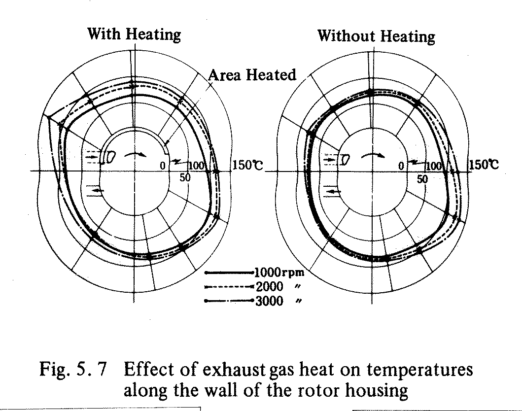
I am not sure I buy this. In fact I have some charts of temp distribution
on the rotor housing and rotor that suggests the area is much larger than
3 by 3. Probably twice or four times that area. I would guess the effective
area for half the heat would be like rotor face dimensions or about 3 by 8 inches.
See the attached side wall temp chart.
K for aluminum is 120 BTU/hr-ft-deg F

200 hp * .5 lb/hp-hr = 100 lb/hr fuel

100 #/hr * 20,000 BTU/lb = 2 million BTU/hr

20% of 2 million = 400,000 BTU/hr heat rejection

1/2 of 400,000 = 200,000 BTU/hr in plug area

Q = A*K*delta T / L

Delta T = Q * L / A / K

Use L = 1 inch = .083 ft.

Delta T = 200,000 * .083 / .1875 / 120  = 737 degrees per inch

Sooo... By this simple calculation it is clear that my claim is in the
correct order of magnitude.  If you want to say less than half of the heat
goes out through this area then use 1/4 and the flux only drops to 368
deg/inch.  Actually, the number is not nearly constant as shown in your
temp graphs and is much higher than average right at the plug.  BTW, I
don't appreciate being misquoted so dramatically.  I said that "200+ deg in
one half inch" would not be uncommon.  That equates to 400 deg per inch,
not the 1000 number you used.
Sorry. My mistake. I just saw "Thus a deeper drill might read 500F while a
shallow drill would only read 300 in the same location where the difference
between shallow and deep is only .5" I missed or misread the ".5" inch.

I specified a hole 1.2 inches deep. Anybody should be able to drill a hole
1.2 inches deep plus or minus .1 inch. The temp given your gradient of 400
degrees F per inch would only be +/- 40 degrees F. However I still think your
gradient is high by a factor of four. So .1 inch hole depth error would
only give a 10 degree temp error... roughly.
That said, having done the calculation
above, I wouldn't be surprised if the number were 1000 deg per inch right
at the spark plug!  Measuring local flux using the temperature gradient of
various depth thermocouples is a tried and true method.  There's no
substitute for experience.

Jeff Spitzer
BTW the Heisler chart is not dimension less. It is drawn to scale so the
temp gradient can be scaled from the chart as the beginning and ending temperatures
are specified. Scaling the the Heisler chart I get about 13 degrees C
through a 1/2 inch wall or about 26 degrees C  per inch or 80 degrees
F per inch.

As a check I assumed the wall near the combustion chamber in the Heisler
chart is 400 F or about 200 C.

Lets say it is 100 degrees F per inch for rounding up purposes.
Using your calculations with about four times the area makes things come out
about right IMHO. I just have an intuitive feel for this stuff :-)

Now I could be way wrong and I will drill two holes with two
thermocouples 0.1 inch apart in depth and see what we get for a temp
gradient.

Paul Lamar


The Aircraft Rotary Engine Newsletter.              Powered by Linux.

http://home.earthlink.net/~rotaryeng/            http://www.linux.org