Ken Powell wrote:
     #3

     Ken P.
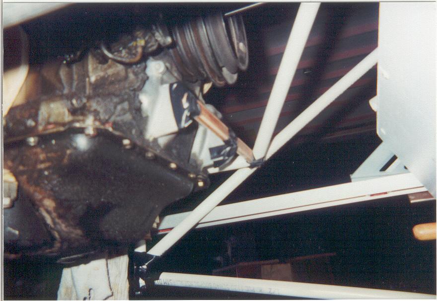
I don't think this method of lateral bracing is going to work.
You need to connect both bipod/mm ends together under the engine
and then use a diagonal from one bipod/mm end back to the firewall or
RV4 landing gear tubes. And X can also be used and the cross
tube deleted.

Make a 1/4 scale model in 3/16 square
balsa wood. It is really effective in finding out which tube
arrangements work and which do not.

The problem with a full scale weak mock like this is the engine
is supported by chains which do not allow you to apply force to the
mount to evaluate its stiffness. Alternatively a mock up could be made
from 1/2 inch steel electrical conduit with the ends mashed flat, holes
drilled and bolted together. That will simulate a proper mount, support
the engine ( a key point)  and you will be able to apply force and
see what moves around.

Paul Lamar

The Aircraft Rotary Engine Newsletter.              Powered by Linux.

http://home.earthlink.net/~rotaryeng/            http://www.linux.org