Paul, i was under the impression that removing the thermostat  will allow
more flow of water but that it would flow so fast that it would not have
a
chance to be cooled of enough when in transit in the rad thus the water
temp
just kept climbing higher and higher. when i was young and thought i knew
This brings up a commonly held "myth" of cooling system design that results
in some penalties in cooling system design.  The coolant does not need time
to "soak up" the heat as it passes through the engine, or time in the
radiator, to effectively remove the heat.  Heat removal is directly
proportional to the flow rate and the temperature change around the loop.
So to remove the required amount of heat (Q), we can either have high flow
rate and a smaller temp change; or low flow rate and a large temp change.
But of course, both of these parameters have limits.  And the Q is fixed by
the max power level we're designing for.

The temperature limit (outlet) for the water based coolant we use is, let's
say, 200 F.  Then the lower the flow rate, the larger the required temp
change, ergo; the lower the inlet temperature.

Now the heat rejection capability of the radiator is proportional to the
difference between it's average temperature and the average temperature of
the air going through.  Then the higher the average temp, the smaller the
radiator can be.  And you can see that with the upper limit on the coolant
temp fixed; a larger temp change results in a lower 'average temp';
therefore the need for a larger radiator.

So, for a smaller, lighter radiator; we'd like very high flow rate.  And as
an added benefit, higher flow rates give higher heat transfer coefficients,
which reduces temp drops at the internal walls; etc..  But, of course, the
flow rate also has limits.  More flow equals higher pressure drops and more
pumping power required.

As most things in life the design is a compromise, but there is usually a
optimum point in these tradeoffs.  Based on data I've seen, and some
analysis, and some judgment; I'd say that the optimum for our systems comes
with a temp change around the loop of 20 to 25 F.  So knowing the heat
rejection required (about 18% of your fuel burn energy in the rotary, about
4850 Btu/min at 180 hp); you can calculate the flow rate needed for 20 - 25
F temp drop.  Its about 35-40 gpm for a 50/50 water/EG mix.  About 25% less
for straight water.

There seems to be very scant data for the coolant flow from the stock Mazda
pumps, but one data point I have is about 36 gpm at engine RPM of 6000.  So,
if this is correct, you NA, 2-rotor guys are about right in there, provided
you pay attention to keeping pressure drops in your cooling loop low.  Above
about 180 hp at 6000, we are going to start paying some penalty in radiator
size, unless we can increase the flow.  For 270 hp (NA 3-rotor) we would
like about 50 gpm to be optimum; or, stuck with 36 gpm, we will have about
35 F temp change around the loop and need roughly 20 to 25% more radiator
surface than at 50 gpm.  Still works, but . . .

This is cursory look at what's going on; and you're probably asleep by now.
And this is just the coolant side of the issue;  The airflow side is
similar, but more difficult because of the vagaries of air flow.  Cooling
system design is one of the biggest reasons for failures of alternate engine
installations, builders don't seem to appreciate that they've got serious
engineering problem to resolve.

Data that we very much need?  Pump flow rate as a function of rpm for a
typical rotary engine loop.

Al Gietzen
In the mean time I am working on increasing the flow :-)
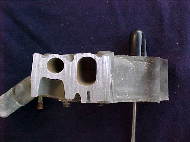
Here is Bulent's 13B Cosmo pump after I cut the top off.
Much nicer and larger return passage. Much smaller bypass passage.
The Mazda pattern making shop is getting better.

Paul Lamar


The Aircraft Rotary Engine Newsletter.              Powered by Linux.

http://home.earthlink.net/~rotaryeng/            http://www.linux.org