"Schertz, William W." wrote:
With Ed Anderson's post of the problems that the GlasStar builder is having
with cooling, I have decided to post some thoughts on things I want to do
before I try to cool the engine in the air.  One of the problems that we all
face is that we don't have sophisticated test facilities, so the common
approach is to build it, fly it, watch it overheat, and modify it.  We are
not alone, a fellow builder (E-racer with IO-540) is having cooling
problems, and has used the cut and try method of changes also, and made very
little progress until he started making some MEASUREMENTS.

We don't know the flow rate through the engine, and difficult and expensive
to put in a flow meter.

We don't know the effect of RPM on the flow rate

Some are modifying pumps to get better flow rate, but without knowing the
baseline we don't know if flow is improved.

Ed's friend has the exchangers in series (which I think is wrong), Tracy has
his in parallel.

I maintain that we need to get some fundamental data on the GROUND on the
cooling system as it will be installed in the plane. To do this I need to
make measurements.  I have attached two figures, FIG1 and FIG2

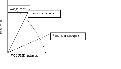
Fig 1 shows how a centrifugal pump interacts with a cooling circuit.  At
zero flow (valved off) the pump will generate a maximum head.  With
increased flow from the pump, the head will trend downwards, until at zero
head it has the maximum flow.  The load for the pump will be a line that
monotonically increases from zero head at zero flow, to a steadily
increasing pressure drop as flow is increased (it may or may not be a
straight line).  The load in our case is the pressure drop of forcing the
fluid through the hoses, the radiator(s), the twist and turns, and the
engine block.  I have shown two lines, one with two exchangers in series,
and another with them in parallel.  When in series, the pressure drops of
the radiators and hoses all add up, and you get a "steeper" load curve, so
the pump has to generate more head, and the flow through the block and the
radiators is reduced.  Putting them in parallel reduces the load, and
increases the flow.

RPM effects on the pump output are to displace the "pump curve" down,
generating less head and flow at any operating point. The net effect of
lower RPM is to trend down-to-the-left on the selected load line.

We don't know the pump curve, and we don't know the load curve, and if we
make a change, we don't know whether we made it better or worse without
flying it and seeing if it overheats. What to do?  Measure the flow as a
function of rpm on the ground.  Here is how:

1.      When I get to the stage of an engine with water pump, I will hook up
the components that I plan on using in a mockup, using the hoses and
radiator planned for installation in the plane. I am not interested in
generating the entire pump curve, just where it intersects my load curve.
2.      Disconnecting the belt from the water pump to drive on the engine, I
will use an electric motor to turn the pump at expected engine rpm speeds.
Speeds will be selected by varying pulley size.  By measuring the flow at
different pump speeds, I will get a map of points (flow vs rpm) on the load
curve.  If the flow is inadequate, I can change components, and try again.
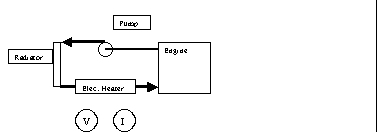
3.      How will I  measure the flow (cheaply)?  By using thermocouples, a
voltmeter, and an ammeter, and a variable transformer.  Refer to Figure 2.

In Figure 2 I have inserted an electrical heating element into the
circulation system (similar to what is done for cold climate block heating).
By powering this element with a variable voltage/current supply, I can vary
the heat input to the cooling fluid.  By measuring the volts and amps, I can
know the power which is converted to heat.

1.      By measuring the temperature drop across the heater, I can determine
the flow, using the equation Q= m*Cp*(delta T) where Q is the heat dumped in
by the heater, m is the mass flow rate, Cp is the heat capacity of the
fluid, and delta T is the temperature rise across the heating element.
2.      Using the mass flow I can calculate the volumetric flow, or just use
it as mass flow.
3.      By blowing air through the radiator, I will dump the heat being
added by the heater, so that a steady state can be achieved.
4.      By varying pulley sizes I can find the flow rate as a function of
pump speed, and then design my pulley selection for the engine to get the
right speed rather than guessing that faster is better, or the problems with
cavitation.
5.      Direct measurement of this type will also ensure that I know the
actual flow-rate through MY engine, with my selected radiator, with my
hosing setup, etc.

That takes care of the water side, now how about the air side?  I plan
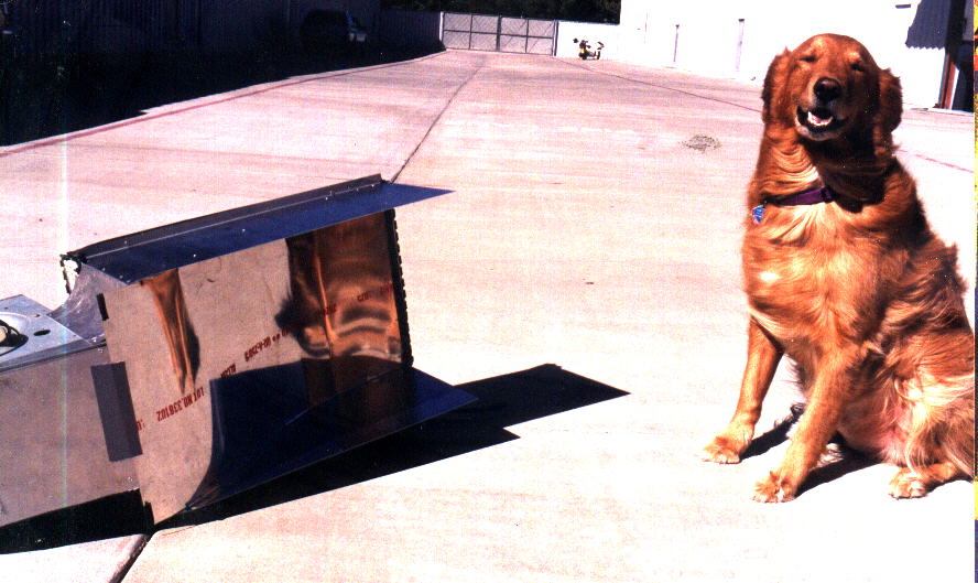
measurements there too.  Paul already showed a picture of a furnace blower
ducted into a radiator for flow distribution measurements.  I plan on doing
something similar, and install a manometer or use an altimeter to measure
the pressure drop across the radiator when installed.  In fact, by running
the heater (mentioned above), I can simulate (or duplicate) the heat output
of the engine, and measure the pressure drop across the radiator needed to
establish enough air flow to cool the water.  Then by measuring the pressure
drop across the radiator during a test flight, I will have a handle on
whether changes to the ducting are required to get better cooling.

I hope this dissertation is useful to others.  I am still a year away from
serious work on the engine and systems.

 <<FIG1.gif>>  <<Fig2.gif>>  <<!TEST-DU.JPG>>

WWS
The Aircraft Rotary Engine Newsletter.              Powered by Linux.

http://home.earthlink.net/~rotaryeng/            http://www.linux.org