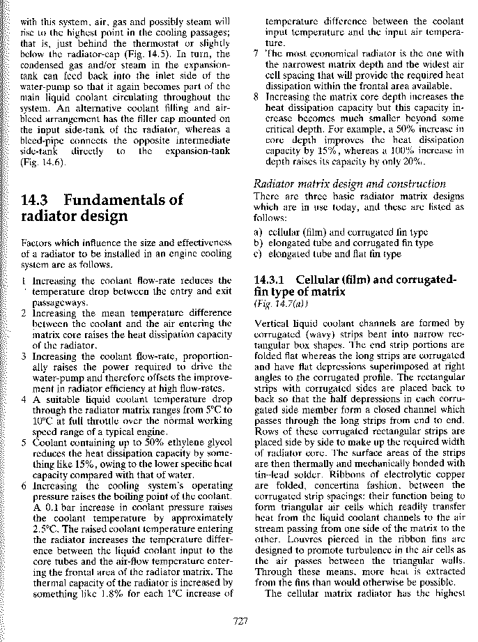
This is an interesting page from Heinz Heislers' book "Advanced
Engine Technology" on radiator design.

Item 7 is why a large area, thin rad located horizontally under the
engine is desirable. If there is no room  under the engine two large
area thin rads mounted on either side of the engine would be my second
choice. In this case the frontal area is defined
as the width and length of the core and not the frontal area
of the airplane. All modern cars subscribe to this configuration.
The inlet diffuser duct(s) must be developed to insure uniform airflow
through the highly angled radiator(s). That means a bell shaped
duct.

Item 2 is why a cross counter flow rad would be desirable for
aircraft use. A cross counter flow rad is one in which hot coolant is first
passed down the back side set of tubes and then up the front side set of tubes
in a two row rad configuration. The typical two pass or three pass design
used in racing cars merely reduces the aerodynamic efficiency of the heat
transfer process as the rate of heat transfer is initially high where the coolant
first enters the rad and drops off rapidly as the coolant temperature is lowered
on its way back and fourth across the rad. Further more this configuration
doubles or triples the restriction of the rad as does the cross counter
flow design mentioned above. Yes the coolant temperature drop through the
rad is increased but it is not the best way to do it from an aerodynamic
point of view. The cross counter flow rad mentioned above is better.

Item 1 is not necessarily a bad thing. What we want is total max
heat dissipation. Item 4 apparently addresses that issue and a temp drop
of 5 to 10 degrees C through the rad is implied to be optimum.
The best flow rate is adjusted to achieve this ideal I would think.

Paul Lamar

The Aircraft Rotary Engine Newsletter.              Powered by Linux.

http://home.earthlink.net/~rotaryeng/            http://www.linux.org