Al Gietzen wrote:
Paul;

I was sending these pics to Chuck, but thought I'd share for anyone who may
be interested.  This is one of two radiators in parallel that will cool the
20B in my Velocity RG.  The velocity is a pusher, and the wing root (from
the spar back) becomes part of the side of the engine enclosure; so this rad
is very close to the engine.  The idea in this placement is to take
advantage of the pressure differential from bottom to top of the wing to
augment the flow of the air scoop and ducting.

The first pic is the radiator; a double pass, two 1 1/4" row, 16 louvered
fins/inch.  If I get 85% efficiency of the air duct, I'll get about 1650 cfm
during climb.  Griffin computed 2,340 Btu/min heat rejection rate for a 90F
day, 200 F coolant inlet, and 18 gpm; and 2 psi coolant pressure drop, 2.5"
water air-side drop.

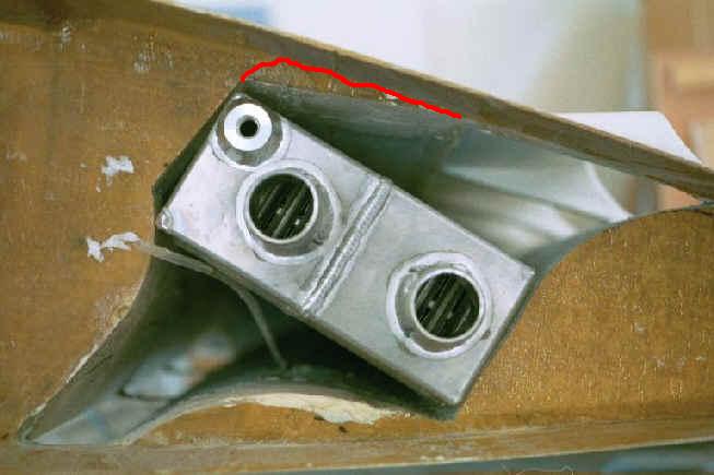
Second pic is end-view of the rad set into the wing cavity (before final
installation) giving an idea of ducting configuration.  Inlet to rad
x-section area ratio is about 1:5. The small fitting is the air bleed which
will be a small parallel loop to a pressure separator tank.

Third pic shows exit duct.

The second radiator will be inside the cowl, and I'll share some info on
that when it's finished.  The opposite wing will have the oil cooler in a
very similar configuration to the wing-root radiator.

Al
I am having trouble visualizing what the intake duct looks like in 3D.
Is it a linear slot on the bottom of the wing?
Do you have a sketch or 3 view drawing?

Here is my suggestions for improving the outlet duct. London and
Kuchemann & Weber both recommend opening this area up as much as possible.

I hate to suggest things at this stage Al because of all the work you have
put in it so far. I will anyway so here goes :-) I think just a set of
variable angle (cowl flaps) metal louvers above the rad would work better.

Paul Lamar

The Aircraft Rotary Engine Newsletter.              Powered by Linux.

http://home.earthlink.net/~rotaryeng/            http://www.linux.org