Peter Nunn wrote:
Thanks tracy, you guessed my plan.
I have been working on a self-powering dual CDI and wanted to adapt it to
the 13B I am planning to use in my aircraft.  The initial work has been done
for a subaru engine that is going into a friends plane.  The cdi uses two
small generators that generate 300v to fire through ignition coils.  Each
module has its own digital signal processor and is self-powered from a low
voltage winding on the generator core.
In the distributor replacement there are two of these (one each side of a
cylinder that replaces the distributor cap and about the same size as the
cap).  There are then 2 sensors that pick up the index and timing pulses to
generate the cdi discharge pulse.
To start the generators a small external starter inverter is used to power
up one side of the system and when the engine gets to idle speed and the
starter is dis-engaged (plus about 2 seconds) the starting inverter stops
and is disconnected from the ignition system.
>From that point on the generators need no 12v power from the system.  They
of course have a disable line that grounds the internals so that you can
kill the ignition system.
As such they are basically the same functionality as a magneto other than if
you don't have 12v to start the engine then the ignition probably won't
start firing either.
So armed with what I am trying to do I have to customise the DSP code in the
ignition modules, but when I looked at the 13B sensors it threw me a bit as
there are too many bumps to make sense of, and I didn't want to hand crank
the engine unless I have to.
I also need to know the ratio to calculate the windings that will be needed
on this engine to generate enough voltage at low RPM while not generating
too much at high RPM.

So back to it.
You say that the upper sensor indicates 30 degrees bdc on the rotor, I am
assuming this is a nominal chamber number 1 on the first rotor.  Which
indicates that the distrubutor will rotate 1 revolution for 2 rotor
revolutions as there are two points on the cam.  Since there are 24 points
on the lower cam these would indicate that there are 12 pulses per
revolution of one rotor or 6 pulses per rotor.  There are however 3 chambers
per rotor so 2 pulses per chamber compression cycle.  I recal someone
posting here that the stock mazda fires the upper (or lower as I cannot
recal exactly) at 15 degrees appart, hence the 2 points.  I understand that
the microprocessor can generate artificial timing signals from the rotation
of the engine pulses but it is much more accurate if you time them from the
lower set of pulses and then delay them to get the advance, I assume that is
what the stock ignition system does.
I guess I am confused by some of the numbers as the engine does not have
BDC, nor TDC so 30 degrees before TDC is a relative term.  I am not that
worried by it however as all I need to know is the ratio between the sensors
and the rotors, the exact timing is set by the time old fashion of rotating
the distributor to the correct timing point.  The advance curves are then
uploaded while running the engine on a dyno.  But I need to know the ratio
of the pulses as well as how to route the cdi firing signals to each rotor
(assuming a 2 rotor CDI).

Hope this is enough information, and the question is:

how many times does the sensor rotate for 1 rotation of the rotor?
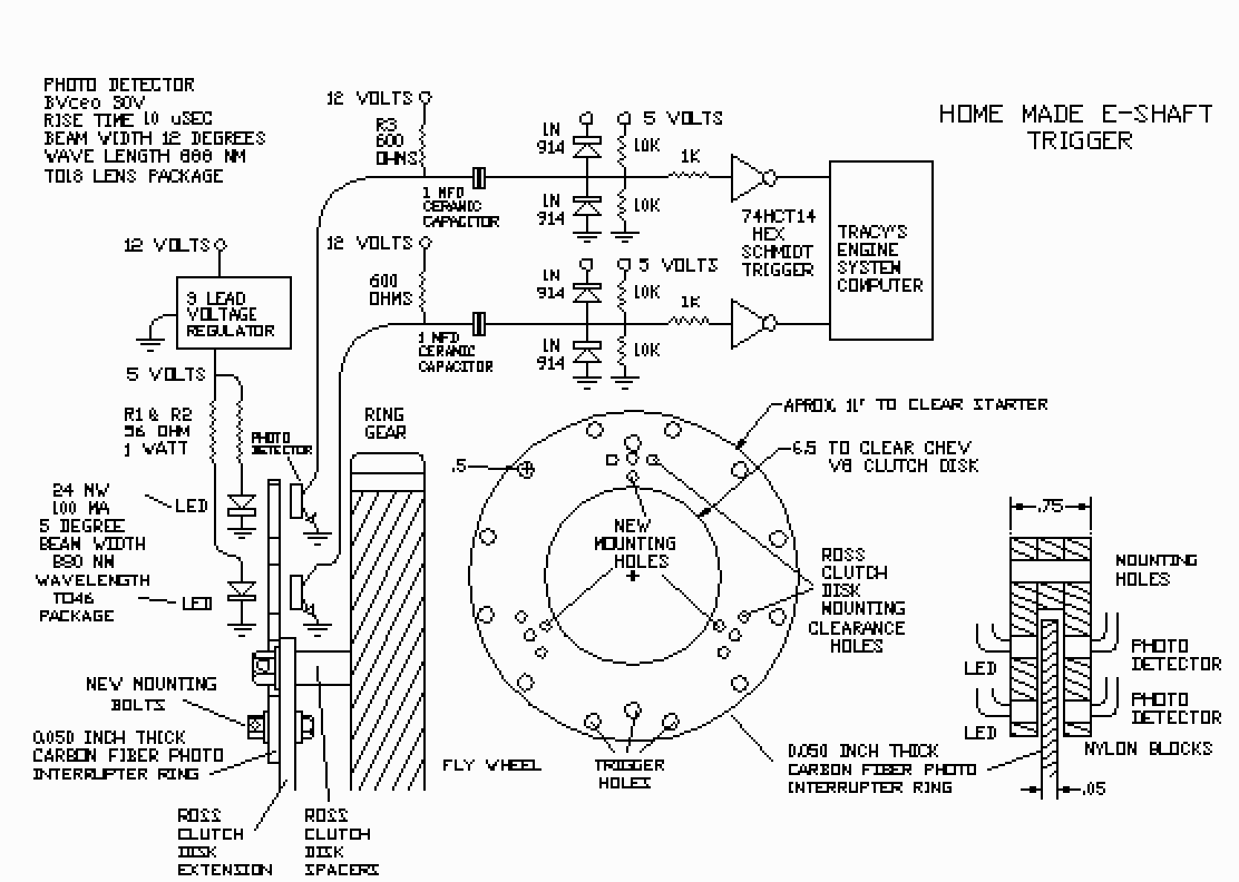
Why don't you build your own sensor that works off the flywheel?
Have you looked at the ACRE NL web site? This will work on any engine.

Paul Lamar

The Aircraft Rotary Engine Newsletter.              Powered by Linux.

http://home.earthlink.net/~rotaryeng/            http://www.linux.org