Bill Freeman wrote:
Make sure that the scoop is thin with knife edges since
you want to avoid any external diffusion with this internal
diffuser.  External diffusion would be caused by wide
rounded lips on the scoop and would increase the inlet
pressure, but at the expense of mass flow.  With a
narrow inlet like that you need full freestream velocity
into the inlet to get the massflow you need, and then
slow it down and increase the pressure in your nicely
shaped internal diffuser.
Bill
Mike Wills wrote:
Bill,

  I think I understand your point above about the impact of external
diffusion on mass flow. I think your comments assume that we are certain
that a proper internal diffuser design has been achieved. Im not sure how
you can guarantee that without lots of testing.

  When discussing inlets with Fred Moreno last year he recommended large
radius lips on the inlet. I think his thinking was that it was highly
unlikely that an eyeball engineered internal diffuser would be successful.
Particularly so in the case of a tractor type airframe with a large rad
located under the engine. He felt that an external diffusion scheme was
much more likely to be successful on a first attempt.

  He recommended the ramped inlet that has been discussed here recently to
insure even flow across the rad core. He further recommended a fairly large
inlet (for my RV4 he recommended 60 - 70 sq in) with large radius lips.
Recommended outlet size was about 80% of the inlet but with a large cowl
flap to allow lots of airflow during climb. Your opinion on this scheme
would be appreciated.

Mike Wills
Mike,
Bill Freeman wrote:
I agree that external diffusion is probably more likely to work the first
try.  I am a
big fan of external diffusers, which are widely misunderstood.  The comment for
Al's design is still valid tho.  He has a diffuser, and is stuck with it as
is unless
he decides to redo it, which would be difficult in the space.  The point I was
making is that he has a small inlet, so to get max mass flow he needs to make
sure he has high velocity at the inlet.  It would be pretty easy to
accidentially
(the way most external diffusion is done) have a lot of external diffusion,
and reduce the massflow to the point that the rads don't cool adequately.
This could happen even if the internal diffuser (which looks pretty good to me)
is a good design.  This sort of error would make it appear as if the diffuser
was not working, which it might if fed freestream air.

The way I see it, he needs to carefully avoid any external diffusion and also
avoid ingesting low velocity boundary air, let the diffuser work (i.e. feed it
high velocity air) and see if it all cools well enough.  If not, the fix
will be to
open up the inlet slot  which partially destroys the internal diffuser,
add a larger, well rounded inlet (external diffuser) sticking well out beyond
the boundary layer and try that.  This will add more drag, since it adds
frontal area.  Lowest drag external diffusion is when you take advantage of
frontal area that you can't get rid of, rather than add new frontal area.

If he can get a clean, knife-edged inlet about 1/2"-3/4" above the skin (out
into
freestream) and keep the velocity up until it hits the internal diffuser, I
think
it has a good shot at cooling with reasonable drag.

Your system sounds reasonable, but I would like to see a sketch.  One of
the best examples of low drag external diffusion compared to low drag
internal diffusion is to look at the cowlings on a F6F or F8F or F4U
(Hellcat, Bearcat, Corsair) which use external diffusion and compare
them to the very elegant and lovely Hawker Sea Fury, which is a good
internal diffuser.  I used to think the Sea Fury was more elegant, and the
Navy fighters crude.  As I became more educated about external diffusion,
I realize that the external diffuser costs and weighs nothing, never breaks
and takes
no time to install, unlike the complex and elegant spinner and internal ductwork
in the Sea Fury cowl.  In the end, both cool ~2500 hp aircooled radials in
about the same space, probably with similar drag.  The Bearcat was tested
with a large spinner, which made it look externally like the Sea Fury cowl
and spinner arrangement.  Apparently didn't do anything for speed or cooling,
as it was not used in production.  I suspect that even Grumman/Vought may
not have
fully grasped the elegance of their external diffusion cowls.  They also provide
local thrust due to low pressure from the lip acceleration, much like Perry's
fan duct.  This local thrust is of course much less than the drag, but partially
offsets the drag.  No spinner is needed because the local airspeed at the
spinner
location is far below freestream velocity.

The trick to external diffusion is to try and find a place where you already
HAVE to slow down the air (front of the fuselage is obvious) and to take
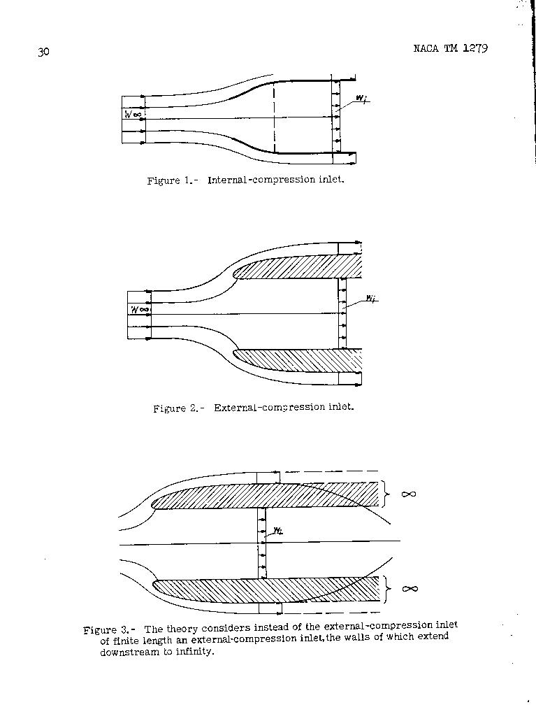
advantage of this.  I have attached a good drawing of the streamlines for
an internal diffuser and an external diffuser.  Note that the streamlines that
enter the inlet for the external diffuser are shaped much like the walls of
the internal diffuser that Al built.  Note that the air is able to "choose"
to expand very smoothly, rather than be "forced" by a particular shape
of an internal diffuser.

I think the info you have been given by Fred sounds reasonable, but I
have no practical experience to reference as to whether 60-70 sq in
inlet and 80% outlet are right.  Paul could speak to this much better than I
from a purely practical standpoint.  The values sound fine, in that you need
to have
a relatively large inlet if your air is already slowed down to get the req'd
massflow.  Accelerating the air at the outlet is very helpful for reducing
drag, but is apparently difficult to achieve in practice, but a smaller
outlet will
have to accelerate the area some.

Hope this helps.

Bill
The Aircraft Rotary Engine Newsletter.              Powered by Linux.

http://home.earthlink.net/~rotaryeng/            http://www.linux.org