Dear Paul and rotary friends,

We have found and solved the cooling problem,

The diverter lip on the top of our inlet was tumbling the
air flow coming down the slope of the cowl from the prop
and spinner. We removed the upper diverter lip so the
air coming down that slope now enters the opening
instead of the tumbled air blocking the incoming air.
Ray
Mike Wills wrote:
  I'm surprised that I didnt see any comments on this. Many folks here have
pointed out the need to get the air inlet away from the boundary
layer  through the use of a splitter or displacing the inlet down away from
the lower surface of the fuse. How ironic that Powersport appears to have
solved the cooling problem by eliminating this feature. No wonder us
rookies are baffled by this whole cooling system design issue. Its
obviously some form of magic. If any of you experts can explain what
happened here I'd like to hear it.

Mike Wills
It is rather unique and flies in the face of logic and
reason. Pardon the pun :-) It is way down and back on the bottom of
the cowling. I checked my photo collection and I can't find any of
the PS intake pictures unfortunately.

All aerodynamic bets are off way down and back there. As Ray said the air is
probably flowing down the front face of the cowl so it is trying
to enter the intake at a 45 degree angle. Since the pressure
in the cowl is about ambient or slightly above there is probably some
external diffusion going on with the air diverted under the intake.
For this reason I am not surprised it is getting more
air with the boundary layer bleed removed. It would probably work
even better if the lower lip was brought forward three or four inches.
IMHO it would work even better if it was brought all the way forward
horizontally to just behind the prop and the boundary layer bleed
restored.

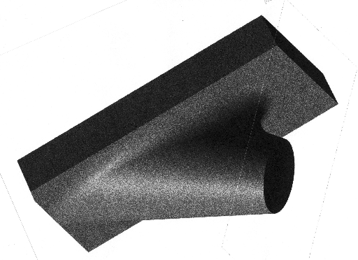
BTW my next door hangar neighbor is more competent in Solid Works
than I am so he did this solid model for me of the kind of
rad duct I have been yaking about for the past six months or a year.
This representation is far from perfect. There is too much cone angle
and the radii connecting the cone to the rad are not large enough but
I hope you get the idea. As I learn more about Solid Works I will be
improving this model in the future. However I am not sure Solid Works
can handle a variable radii between intake cone and radiator face.

Paul Lamar

The Aircraft Rotary Engine Newsletter.              Powered by Linux.

http://home.earthlink.net/~rotaryeng/            http://www.linux.org