The other factor is rad
thickness. Rad thickness must be kept to two inches or less to insure
adequate
cooling mass air flow at climb speeds around 100 MPH. A 100% effective duct
will generate 26 pounds per square foot or a pressure of 0.18 psi across
the rad at 100 MPH. A typical duct will be about 80% efficient so that is
only 0.14 psi. This is why a thin rad is called for in GA airplanes.
Paul Lamar
Al Gietzen wrote:
Whoops.  I think B does not follow A.  The computed pressure drop through my
3" thick core (2 rows of 1 1/4 tubes) is 2.6 inches of water; about 0.1 psi.
This is for a flow velocity through the core of about 25 ft/sec; which I
think is about what you would get for your 80% efficient duct at 100 mph if
your radiator area to intake area ratio is 4.5 - 5 to 1.  (I designed for
125 mph climb - 0.28 psi dynamic pressure - and an area ratio of 5.2/1)

I recall Freds analysis showing the minimum drag (all other things being
optimum) is achieved with thicknesses of 2 - 2.5 inches; but I don't think
there is any reason not to use a thicker radiator to get the heat transfer
area you need; and (perhaps) taking a small drag penalty.  And this
particular wing installation allows for fairly optimum inlet AND exit
diffusers which will likely result in lower drag than, say; a radiator in a
cowling where there is no ducting at the radiator exit.  IMO, the "right"
radiator thickness depends a lot on your particular installation; how much
you slow the air down; and then there is the whole other list of variables
including tube spacing and the number of fins/inch.

Al
Well lets say we go up to 3 inches thick. The length required for 600 cubic
inches would then be 600/(7*3) or 28 inches long. Or two rads 14 inches long.
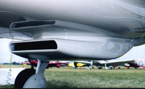
It will be very hard to bypass the boundary layer with a duct that wide
under the wing. You will need two ducts that externally look like the picture
below. As I recall the owner of this V6 powered airplane complained about
the drag.

IMHO the best place for an intake duct with a wing mounted
rad is in the leading edge as many World War II airplanes had. The best place
for the outlet duct is sort of a split flap trailing edge. In that
case you need to get the air past the spar somehow without causing a lot of
internal drag in the ducting. One of the ways of doing it is use a porous
truss spar made from streamline tubing diagonals. In World War II the
designers designed the wing with internal rads in mind. I don't know how
you would incorporate that into a composite wing or a sheet metal wing
for that matter after the fact. I think it would be very tough to do. I
still feel the best place for the rad is under the engine in the cowl.

Paul Lamar

The AirCraft Rotary Engine NewsLetter.              Powered by Linux.

http://home.earthlink.net/~rotaryeng/            http://www.linux.org