Tracy Crook wrote:
Maybe the enclosed scale drawing of my engine and airframe will help some of
you guys to decide on starter location.  The rad shown (19" long x 2" thick)
is just shown for illustration.  When I try to stuff the sample radiator up
into where the starter is, it looks pretty ugly to me. If you don't have a
CAD program, print this out,  make a paper doll cutout of the radiator and
play with the position.  I can envision a fairly clean inlet and diffuser on
the lower cowl that would work pretty good.  This might even be a usable
spot for a NACA scoop.

To my way of looking at it, the space occupied by the starter is not very
useful for anything else.  Even a duct at that location isn't very
promising.  The RV-4 engine bay shown here is taller than some and shorter
than others.  Total vertical height at the firewall is 31 inches.  I know
this is substantially more than the Glasair (I'm working with a Glasair
flyer on his rotary installation) and pretty sure the Lancair is just as
short.

One more time, If you haven't done a drawing like this for your airplane,
it's way too soon to decide starter location.

After you've done this and decided on a different location, I'll be glad to
furnish a CAD drawing of the adapter plate & hole pattern.

I'll upload some pictures & words on the illfated exhaust system soon.

Tracy Crook
rws@altavista.net
www.rotaryaviation.com
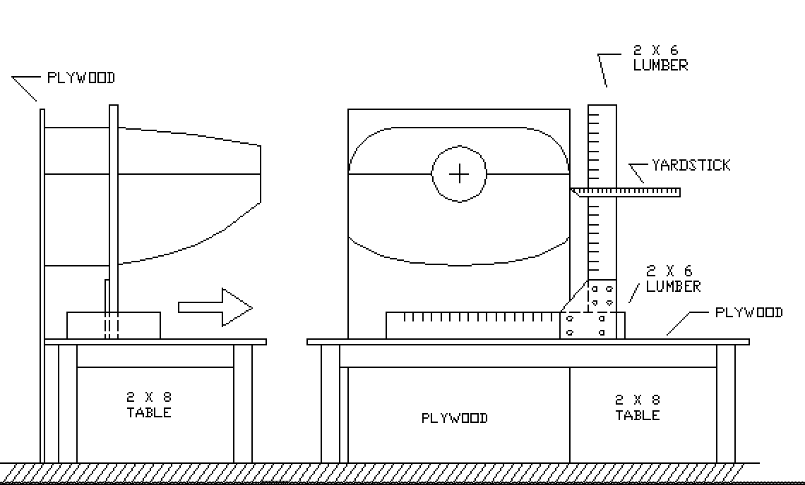
Back in the old days before solid modeling programs on computer
work stations became available we used to design car bodies like this. First
a full size clay model was made of only half the car. Right or left half.
Then a rig something like this was used to measure the coordinates of
every spot on the surface of the clay model on a one or two inch grid. Then
cross section drawings could be made of the outside shape of the body.
These drawings  were then sent off to the die makers to make the dies that
stamped out the fenders, roof, hood and so fourth.

The same technique can be used to make cross section drawings of your
cowling if Van or the designer of your airplane did not
include them in the plans. Once you have done this you then
can make cross section drawings every two or three inches of
the internal parts of your cowl to check the fit of everything.
If you do this upload the cowl cross section drawings so the next guy
will not have to do it for his cowl if he has the same kind of airplane
kit as you do.

BTW use a small level to make sure the yard stick is square to everything.

Paul Lamar

The AirCraft Rotary Engine NewsLetter.              Powered by Linux.

http://home.earthlink.net/~rotaryeng/            http://www.linux.org