Turned this up out of the woodwork. Not 'quite' right,  but getting closer to the TRUTH!

http://www.prime-mover.org/Engines/Images/aio_eng.jpg

Leon Promet
Kelly Pernell wrote:
Hi Paul,
 Sorry for the delay in responding. A fellow RV List member sent me cocktail napkin sketches for building an inverted oil system "slobber pot" and oil feed / breather "switching valve". These units are used on many Christian Eagles. It is a much simpler system than the Lycoming system that Leon referenced. It is similar to the Aviat system. See

http://www.prime-mover.org/Engines/Images/aviat.html

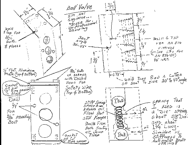
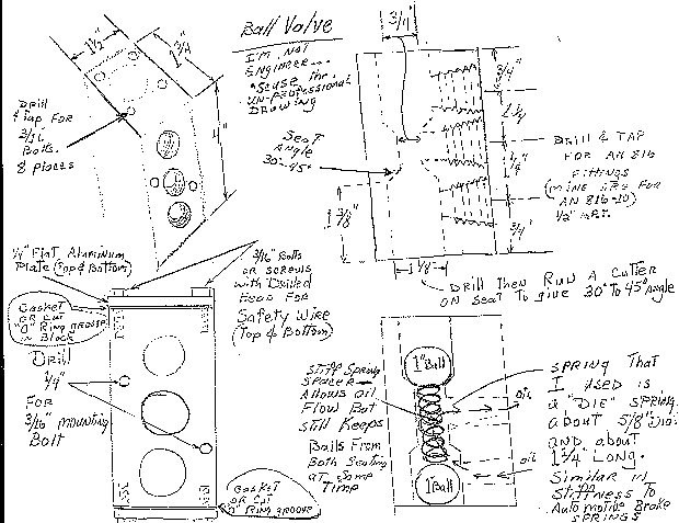
 When the time comes,  ( at least a year) I intend to make up several sets of these for the local RV builders who are interested. A good, cheap basis for the "slobber pot" is a GM Air Conditioning accumulator. Cut the top off, remove the guts, and weld a top plate and the needed fittings on.
 Fellow RV builder Peter Laurence converted the oil valve sketch to CAD. However, the details for the check ball seat angles, spring tension, and check ball to wall clearances still have to be determined. Perhaps you can improve on these? Hopefully, this info will jump start this thread back to life!!  :-)
 I have some other inverted oil info I've gleaned from folks who have them installed.
Charlie Kuss
RV-8A fuselage
Boca Raton, Fl.

                                    Building Your Own Inverted Oil System

 Here is first part of this subject. You will like the outcome of this plus it will save a bunch of bucks. After all we are
Homebuilders and we should be doing this if we can. As you send me questions, I'll answer them to this group. This first
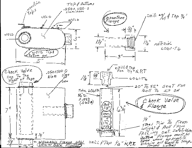
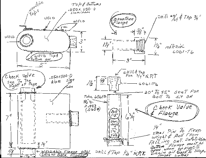
drawing depicts the OIL SEPARATOR, sometimes called the "slobber pot". I have drawn it sort of oval, as AcraLine made
them. You could also build it out of 5" diameter round pipe. The oval version is a little more compact than the round.
  This system was developed by IAC members and isn't patented. Notice the check valve and flange. I made mine out of one
solid piece of stock to avoid the need for welds.
(Poster's name removed per his request)

I found this good engine site. http://www.prime-mover.org/engines/pictures.html It shows the inverted oil system upright and
inverted. I was going to scan this and send it, but he saved me some time and it is excellent. I would not even consider the first
one listed. The Aviat system (2nd one) is what is on Pitts and Most other airplanes. The one from Acra-line (3rd one) is almost
Identical in operation and layout as the one from Aviat. Aviat is actually the Christen system. I think the Acraline system was
actually out first. But he makes some real high tech stuff for the aerospace industry and these were only done as a hobby back
when he competed. He used to get $75 for the ball valve and about $150 for the separator. I'm sure if he would run some off,
they would be more but I haven't seen him advertising for a few years. His name is Nathan Davis and he is in Indiana around
Peru or Kokomo area. It would be interesting if some one in the vicinity would check this out.

Up at the top (about a 1/4" below the ball seat) there needs to be 6 holes drilled around (and into) that tube. These holes are
part of the crankcase breather system in up-right flight. When inverted, they do nothing and the ball will seat, closing that port.
On the Christen oil pot the long tube has holes drilled in each end. On the drawing I sent, I just left the bottom end open. The
reason I showed it open was that I machined this tube from a piece of round rod and it was more convenient to do this way. In
other words, the top fitting "boss" is part of that tube in mine. In some systems they weld both ends of the tube into those weld
boss's and drill holes near the top and bottom for breathing. I'll send a scan of Aviat's pot later so you can see it but it will be
just for reference. Don't anybody dare tell anyone that I sent copywrited material.

(insert oil10.jpg here)

 I have attached the ball valve scan here. It is easy to build and understand. The one I measured from is on the desk here. It is
milled on all sides from a larger piece of stock. I had two of them made when I worked for Winchester Ammo at E. Alton,
Illinois. I used one on a 150 Pitts I had then. The one I have on the 180 Pitts now is Acra-line and it looks like he found a stock
size (about 1 1/2 X 2 ) extrusion at some metal parts supplier and cut off 4 or 5 inches and drilled it out. nothing critical at all
here. I like the size I sent you because it is compact and works. The stiff spring is used as a spacer to keep both balls from
seating at once while still allowing oil to flow through which ever port is open. The Christen valve is larger and more massive.
One advantage is it has two sets of identical ports placed 90 degrees from each other. The purpose of this is to bring a fitting
and hose out a different direction if you need to. You put a pipe plug in the 90 degree ports if you don't want to use one of
them. I have not seen any problems with any valves.

  I'll send some sketches of some changes you will need in the fittings to your sump later. These just allow the oil pump to come
out and get hosed to the middle port of the ball valve instead of sucking on the screen in the sump.
The AirCraft Rotary Engine NewsLetter.              Powered by Linux.

http://home.earthlink.net/~rotaryeng/            http://www.linux.org