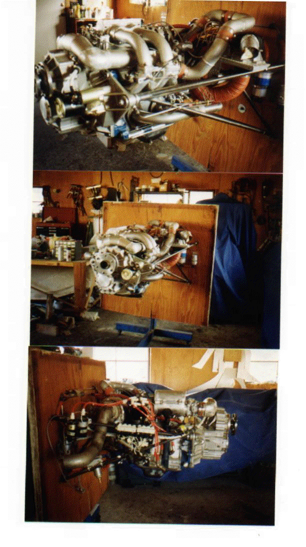
This is a first installment in a series  of descriptions of what I did with a mazda 13b installation. Enclosed are some pictures of the airplane and the engine installation. The engine configuration is version 1 it has since been slightly changed because of information learned on the test stand. I also will speculate about a better way of building the power system.

Starting at the prop and moving back I will describe the gearbox this time and the engine next time.

The  prop flange is a SAE 2 good for 200 hp or better on a conventional prop. I am using a wooden prop. Perhaps you can see in the pictures that I added a short extension to increase the diameter if the prop-flange interface to 8". At my airport we have several longeze aircraft with  0-320 and 0-360 engines. Experience has shown that the standard SAE 2 flange has marginal torque carrying capacity. One plane has a seriously hopped up 0-320. With an estimated hp > 220. This plane has lost several props from inadequate prop bolt torque. The wooden props compress at appropriate bolt torque and the prop becomes loose. If it is not too loose the wood finish just chars. If it is too loose the prop departs from the aircraft. Fortunately the longeze is a good glider with the prop missing. I chose 8" as the interface as a compromise of weight verses area. In testing the interface works well with 30 to 40 ft/lbs torque on the bolts. This torque does not compress the wood of the props I h!
ave.

The drive shaft is 2.25 od and is hollow. A ball bearing which is capable of both axial and radial loads supports this end of the shaft. An oil seal is between the bearing and the prop flange. The drive shaft is splined and a gear is heat shrunk on the splined portion of the shaft. The gear is quit a bit bigger than the shaft. Although the gear has a thinned web between the splines and the teeth, the gear is quite heavy. Massive really. The other end of the drive shaft also has a ball bearing on it. It also takes both radial and axial loads. The bearing is enclosed so that an oil seal is not required.

The input shaft has one ball bearing on each end. The prop end is enclosed and an oil seal seals the other end. The input shaft is internally splined and the shaft from the engine floats inside the input shaft. Axial motion of the engine shaft is limited forward by a nylon button and backward by the pilot bearing in the eccentric shaft. Motion is about 1/4".  Oil sealing on the engine shaft is by a couple of large o-rings which ride on the engine shaft and press on a smooth non splined portion of the hollow input shaft.
This configuration worked well with excellent oil sealing. After 50 + hours there was no apparent wear on the o-rings.

Between the engine and the gearbox is an industrial coupling made by Dayton industries. It is a hat section of rubber and fabric on the flywheel side it attaches with a compression ring and bolts. On the gearbox side it attaches by compression/friction to an internally splined steel/aluminum piece through which the torque is transmitted to the engine shaft then to the input shaft. The coupler is quite "dead" in that it has very little spring or bounce similar to a auto tire that is deflated. Strobing the part shows that it does move some with torque pulses. The configuration never puts this coupling or the engine  shaft in carrying radial loads only torsional loads.

The engine has an automatic counterweight on the eccentric shaft and an aluminum flywheel bolted to it. The flywheel has the ring gear for starting and nuts for bolting the compression ring to the flywheel. The compression ring is what helps transmit torque to the rubber coupler.

The gearbox is supported by a custom cast bell housing which supports the starter. It is a tilton unit. I have had good luck with these in the past. They also have many gears for the starter so that just about any common ring gear can be use.

The gear housing is cast aluminum. It is probably much heavier and stronger than it needs to be. However I was limited  in thickness by the foundry.

Now let me speculate a bit on  better ways of building the gearbox.

First a lighter housing could be made by cnc maching the unit in three pieces- a front and back cover and a center section in which the gears turn. The bearing carriers could be separate pieces bolted to the front and back cover.  This would make assembly and disassembly much easier. The seal the various pieces o-rings instead of gaskets would keep clearances constant and do just as good a job of sealing.

Second  I would change the output shaft. I would make the output shaft a hollow tube the diameter of the SAE flange. The  large gear could be cut into the OD of the output shaft or better yet the shaft splined and a gear with internal splines and external teeth could be heat shrunk onto the shaft. The prop flange is machined onto one end of the output shaft. A caged roller or caged needle bearing of rather large size would support the prop. On the other end a tapered roller or ball bearing which support both radial and axial loads is inside of the shaft retained by circlip or threaded collar. Thus all axial loads are taken by this bearing. This makes the adjustment of the shaft and bearings non-critical. And makes assembly of the gearbox simple. This type of arrangement could also be used by a belt driven reduction unit as well. Since the output flange (prop flange) is the same diameter as the shaft , installing the bearing behind the prop would require no disassembly of the g!
ear off the output shaft. Again making the unit simple to work on if necessary. Since the output shaft is large diameter the wall thickness can by quite thin to support the bending loads from the gyroscopic forces on the prop. It also can be short since the non-prop end is supported by an internal bearing again of considerable size. As well since the output shaft and the large gear or toothed pulley are nearly the same diameter the housing in this area would contain less material thus less weight.

Third I would change the input shaft also. I would build it like the output shaft but put on a removable flange on the input end. The flange could be bolted and  pinned to the input shaft thus making disassembly easier. Another reason for the flange follows.

Between the gearbox and the engine I would put two large diameter plates one attached to the engine and one to the gearbox. The gearbox is piloted on the eccentric shaft of the engine. To transmit torque one plate has large spigots on it The  other plate has holes  with flanges in which are captive sorbathane (sorbathane.com) heavy wall bushings. Thus the elastic material is the buffer between the two plates.
As an example of this is subielyc (subielyc.com).  they are slightly different.

I do not like the fact that the prop turns the opposite direction but 1 or 2 idler gears which could increase the gear tooth area would add too much weight and complexity to the system. The idea is to keep the weight DOWN.

Below are some pictures of my airplane and the first engine iteration. The turbo setup was changed from high above the engine to low beside and behind the engine. The exhaust manifold was changed from a several piece unit to a single piece unit. The multiple piece unit had slip joints around a 90-degree bend. As the tubing expanded and contracted it changed the bend angle which made the ends of the piece shorter. The slip joints fell apart while the engine was running on the test stand. I considered bellows type flex joints but could not find a suitable material (321 SS or inconel) of sufficient thickness to be safe. Thus the single piece to the turbo. The single piece is probably safer in failure  anyway as long as expansion is
Taken in account BECAUSE OF LESS PARTS.

C.L. Smale        Smale@ncinternet.net

Paul Lamar wrote:
Incredible installation.
Thanks for taking the time to upload this C.L..
that is a real cool motor mount that looks kind of familiar. Maybe I did not invent
that motor mount  after all :-)
Thanks again for sharing this.
Paul Lamar
The AirCraft Rotary Engine NewsLetter.              Powered by Linux.

http://home.earthlink.net/~rotaryeng/            http://www.linux.org