Paul Lamar wrote:
I don't fault you for taking that position. I would do the same if I were
in your shoes Tracy.

Send me a sketch of that counter bore Tracy and I will accommodate it in
the drawing. If some of you wish to wait until I test it a bit that's
fine.
As far as the vibration isolation I think Jeff's analysis is flawed.
Engines don't rotate one degree no matter what. Angular deflection
due to torque pulses depends on the restraint.

The torque pulse amplitude however is constant at a give HP level. With
wide spread
rubber bushing of the same rate the torque pulses are half the amplitude
therefor the deflection of the rubber is half as much. Torque is in foot
pounds.
200 foot pounds is 200 pounds at a one foot radius and 100 pounds at
a two foot radius. Something Jeff did not point out.

Also the normal 1 G load on the spacers is less with the motor mount plate
because if you put the motor mounts on the engine the spacers must
accommodate
prop torque which is roughly twice as much as engine torque due to the
reduction ratio. On the other hand when the motor mounts are on the plate
the spacers only have to deal with half the prop torque or engine torque
alone. Therefor spacer deflection due to prop torque is less and not more
with the motor mounts on the plate rather than on the engine.
Do you agree Tracy?

I think you should offer this plate as standard equipment Tracy :-)

Paul Lamar
Tracy Crook wrote:
Thanks for appreciating my position on this Paul.  It is definitely not
meant as a criticism of your efforts.

The counterbore on the latest version of the adapter plate is .030" deep and
2.040" in diameter.

On the vibration isolation question,  I think it boils down to this:
Assumeing that the appropriate compliance is engineered into the isolators,
there is no difference between closely spaced or widely spaced engine
mounts.  The analogy I would use is the torque on a pair of gears having the
same diameter and number of teeth.  The torque transfered to the driven gear
shaft (the airplane in this case) is the same regardless of the size or
number of teeth on the gears.

The one disadvantage to the widely spaced mounts is that a very compliant
(large displacement) isolator is needed.  This may be harder to implement.

The issue about the stress on the adapter plate concerns the TYPE of stress
involved.  You are correct about the spacers seeing less torsional stress
with the universal plate.  But torsional stress does not concern me because
this will not result in any lateral displacement of the plate.   Mounting
the engine by the plate does put lateral stress on the plate which will
result in moving the drive out of concentricity with the engine.  The
obvious question is "By how much and will it matter?".  I don't know the
answer to this because it will be VERY dependant on the spacers used.  My
design goal was to keep things concentric within plus or minus .001"

On the question of weight, I will be very interested to see how it turns out
compared to what I have planed for my RV-8 (see website for the engine mount
design).  If yours turns out to be lighter I'll be kicking myself all the
way across my runway!  :-)

Tracy Crook
rws@altavista.net
www.rotaryaviation.com
All good points Tracy. Your spacers can be used of course.
I weighed the plate today and it is 12 pounds verses 8 pounds for yours.
That is without lightening holes which are easy to add if we get it
hydra cut. I think we could save almost two or three more pounds with
lightening holes.

Hard to build a couple of motor mount brackets that weigh only
2 pounds apiece, clear the outside of the turbo charger or a
tangential muffler, free up a bunch of room under the engine
for one big rad and fit all three generations of 13B and some if
not all three rotor engines. :-) Cheap to build too if YOU
had them made :-) It has taken me 2-1/2 years of thinking about it.

As far as my spacer system is concerned it would be stiffer than
yours as the 14 inch diameter 3/16 thick rolled aluminum sheet metal
would be welded to all spacers acting as shear material and
a like cast alloy bell housing. I will fly the airplane before I
do that as it is strictly cosmetic. I don't anticipate any weight
saving over your spacer setup.

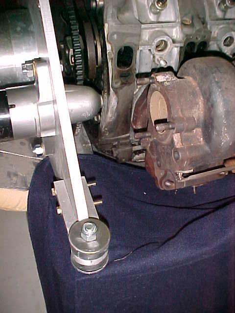
Here is a picture with the starter mounted. I mounted it on the
e-shaft horizontal lateral center line so it is easy to set up
for boring the starter pilot hole in a mill. More about that
shortly.

As far as I can tell those starter bolts are 7/16. Is that your
understanding? 12 mm seems too big and 10 mm seems too small.
I can't find any 11 mm metric bolts in Santa Paula :-)

An interesting aside. Back in the old days 1965 when I was designing race
cars I decided to mount the rear spring shock suspension units directly
to the engine transmission unit on the Chaparral 2F. Traditionally
the spring shocks were attached to the chassis and the engine
was  mounted into the chassis. All passenger cars are still
done this way today. I had a heck of an argument with Jim Hall
over this. I am not saying that I invented it because one never
knows for sure if someone did not think of it long before I did. Now
a-days all rear engine and a few front engine race cars are built
like this and so too is the Questair Venture front landing gear.

Another example of this is the single engine Grumman fighter planes
of World War II. All had the motor mount bolted directly to the wing spar
and not the fuselage. The F8F Bearcat was the ultimate manifestation
with a very short motor mount. All twins of course are done this way.
The basic idea is to make the load path to the mass that
reacts the dynamic loads as short and as direct as possible. This
eliminates a lot of structural weight. This motor mount plate
design adheres to that principle.

Paul Lamar

The AirCraft Rotary Engine NewsLetter.              Powered by Linux.

http://home.earthlink.net/~rotaryeng/            http://www.linux.org