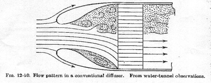
The key is to look at the inlet area of the intake duct required to
cool the engine. This assumes a perfect diffuser so the air velocity
through the core will be lower and drag through the core like
any aero drag is proportional to velocity squared. Make them diffusers
bell shaped guys or you will never notice this advantage.
I'm missing some little piece here. I see the scaled pressure on the
wall of the diffuser flattening out with the bell shaped diffuser as the
face of the radiator is approached. What am I supposed to glean about
drag from that? I'm just not making the connection yet.

Thanks,
David
The pressure recovery is better with the bell shape so less radiator area
is required to generate the same cooling. In the traditional, perpendicular
to the air stream, radiator this results in less aircraft frontal area.
In an imbedded radiator in the aft fuselage for example the inlet duct
area required would probably be smaller with less external diffusion
disrupting the airflow around the aircraft.

Best to get a copy of Kuchemann & Weber Aerodynamics of Propulsion.
Long since out of print but check the web for used books.
Paul Lamar

The AirCraft Rotary Engine NewsLetter.              Powered by Linux.

http://home.earthlink.net/~rotaryeng/            http://www.linux.org