Jerry Hey wrote:
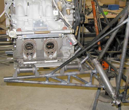
Hi Paul,  I spent the last two days building my engine mount.  I
failed to achieve my goal which was to keep all the structure below
the engine.  When I placed the engine on the mount, it sagged
downward nearly .25".  If I were to do it again, I would factor this
in.  I pulled the engine back off and put in the top braces.   Seems
to be solid now.  Only about half of the welding is completed at
present.  I'm sending several photos.  You probably will not want to
use them all. The vibration dampers were made by inserting a 3/8"
I.D. hydraulic  hose inside of a 3/4" hydraulic hose which it fits
perfectly.  The result is a 1.25" O.D. rubber bushing with a  .375
hole.  This is inserted in a piece of 4130 bored to exactly  1.25
i.d.  The rest is made clear from the pictures. ( I got this idea
from Jess Myers)  I could have done a better job making the dampers
as well......oh well.  Maybe I will do them over.    I made
everything myself for less than $10.00.

In the photo the engine is just setting there, the attach brackets
are not welded in place.  This leaves me the ability to move the
engine forward or back 2" from its present position. I still have
unresolved c.g. issues with the fuselage rad.  The engine hoist is
just for security. It is not holding any weight.
Jerry
The compressive load on the lower member joint (original configuration) I
would
guess to be about 600 pounds static and 3600 pounds on a 6 G landing or
pull up.
That amount of load needs to go into a cluster joint and not in the middle
of a transverse tube. Same goes for the upper member. Looking at the
pictures
I would guess those two members are only six inches apart back near the
firewall.
The CG of the engine is roughly two feet from the firewall. Assume the
total
engine/PSRU/prop/starter/alternator weight is 300 pounds. So the total
bending
moment is 24" X 300# or 7200 inch pounds. Each side handles half. Dividing
by
six inches gives the compressive load in the lower joint and tension load
in the upper
joint of 600 pounds. Of course your fix drastically improved the situation.
It
is always best to weld motor mount tubes into a cluster of tubes and not
into
the middle of a tube when doing motor mounts for space frame based
fuselage's.
This picture illustrates the point best.

Paul Lamar
George Lendich wrote:
Paul,
Any chance seeing the hydraulic hose dampers.

George (down under)
The front mount takes 80 to 90% of the load as the engine/PSRU/prop/starter/etc.
CG is located right about the joint between the front (rear in the car) rotor housing and
the front (rear in the car) end housing. The rear mount length could be cut way down
and still work fine. BTW this mount could work fine without the long diagonal side braces
and with a little strategic beef up of the fuselage. Let me know if you are interested
and I will mark up some of the pictures to illustrate. The penalty would be higher
weight over a  more traditional type engine mount.

Paul Lamar

The AirCraft Rotary Engine NewsLetter.              Powered by Linux.

http://home.earthlink.net/~rotaryeng/            http://www.linux.org