"Rosine, Steve" wrote:
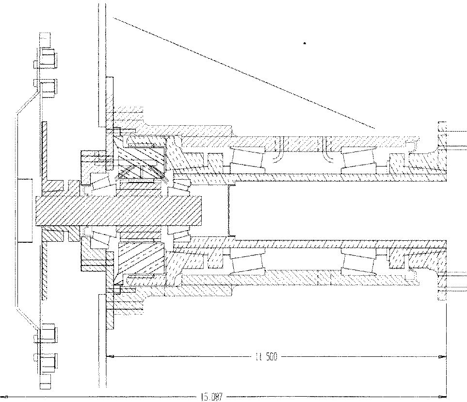
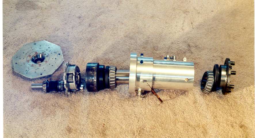
The time has come to publish my PSRU work.  This is an original design with
features borrowed from others, and what has been discussed the last couple
of years on this list.   The design goals were reliability, cost and ease of
maintenance.  The design originated from Paul's tubular shaft design
published on the ACRE web page.  Major changes from this design were the
addition of a rear input shaft bearing, use of all taper roller bearings,
and the QD bushings instead of shrink fits.  Overall weight is 43 lbs.,
including backplate and torsion isolator.  I estimate my costs to be about
$650-700.  Some machining was contracted out, some I did myself.  I did all
the welding myself with TIG.

Here is a parts description and the assembly sequence:

Input shaft:    1" dia Thomson hardened shaft  Bought thru McMaster-Carr
($18).   1" long section of stock sun gear TIG welded to shaft with an
adapter sleeve made by local machine shop.  Washers used to select spacing
between sun gear and bearings.  Constant force on front input bearing
maintained by belleville springs.

Output shaft:  2-1/2" dia. x 3/8" wall x 10" long Thomson tubular case
hardened shaft.  Outer 8" of length bored out to 1/4" wall for weight
savings.  Other end has machined recess for input shaft front bearing.
($90+machining)

Propeller hub:  Modified from steel sprocket with QD hub (size SK rating 580
ft-lb + Loctite retaining compound).  Hub diameter reduced slightly to fit
oil seal.  Sprocket diameter turned down to 6".  Flange thickness about 3/8"
.  Drive lugs welded to face after drilling for prop bolts.  ($39 sprocket +
$14 QD bushing)

Ring gear:  Stock ring gear with bulkhead removed, then welded
concentrically (.003" TIR) to modified steel sprocket with SK-type QD hub.
($32 sprocket + $14 QD bushing)

Planet carrier:  Stock Ford C6 4-pinion.  One of the open spaces between
pinions was filled with JB Weld, then drilled for input bearing and sun gear
oil passages.  Each of the fingers has been drilled for an 8-32 screw.
These screws are in double shear between case and subplate. It would have
been very easy to install the new 6-pinion planet carrier, but it wasn't
ready when I started this design.

Case:  Machined in two pieces from heavy wall 6061T6 tube.  Shrink fit
between tubes.  Inner tube went in freezer, outer tube in 250°F oven.  Slip
fit at this temp difference.  Material from Metal Express ($80 for
materials, $240 machining)

Subplate: 3/16" 6061T6 sandwiched between backplate and case flange.  This
was to make the PSRU completely separate from the backplate.  This is
non-structural, but did allow positioning of the input shaft rear bearing
housing to make input and output shafts parallel without having to position
the PSRU concentric to the torsion damper/driveplate at the same time.   The
subplate has steel inserts installed for the rear bearing housing screws.
The force from the sun gear helix angle is sufficient to strip threads in
aluminum

Backplate/engine mount adaptor:  1/4" 6061T6 positioned off engine face with
3-1/4" long hexagonal aluminum standoffs.  3/16" aluminum web welded between
two pairs of standoffs for torsion resistance.

Backplate bolts:  The longest bolts I could find in 10mm x 1.25mm were 100mm
long.  These fit thru the backplate  and spacer and engaged the threads in
the engine flange in only 3 of 6 places.  The other threaded holes in the
engine flange were re-tapped for 7/16"-14.  I was able to find grade 8 7/16"
bolts to fit at the local hardware store.

Torsion damper/drive plate.  Very similar to Tracey Crook's.   Drive plate
is 0.040" 4130 with four aluminum blocks riveted on.  Blocks have 1-1/4"
hole to accept short neoprene bushing (cut from tube available from
McMaster-Carr).   Four drive lugs are welded to automatic transmission
flywheel using torque converter holes.  These pass thru the rubber bushings
and are secured with large washers.   In the center of the drive plate is
another QD bushed sprocket to connect to input shaft.  This sprocket is
SH-size (290ft-lb rating)

Bearings:  All Timken taper-roller type, and massively over-sized.  Prop
shaft is supported by opposed 3982/3927X (7500lb radial, 5100 lb thrust 90M
rev. rating) bearings.  Input shaft rear bearing, which takes the gearset
thrust load is 23256/23100 (2950lb radial, 3700lb thrust, 90M rev. rating)
Input shaft front bearing,  which is possibly not needed at all as it should
only be loaded during start/stop/idle conditions is L44642.   This bearing
is subject to very high rotational speeds-- the cone is rotating at 6000 rpm
with the input shaft, the cup at 2764 rpm in the other direction with the
prop shaft.  I cleared this with Timken engineering, but I keep the bearing
well-oiled and am glad it carries virtually no load.  All other bearing
speeds are well within design limits.

External stiffening rods:  Not installed at this time.  However, 3 AN-style
eye bolts are installed with steel inserts into the case just behind the
prop flange.  Stiffener rods could be attached to these easily.  Current
mounting to engine appears very stiff.

Lubrication:  Self-contained gear oil lubrication.  A ring gear scraper is
built into the case to help scavenge the oil.  This is a v-shaped ridge of
JB Weld with the outlet hole inside the apex of the V.  Idle tests show a
lot of oil flow from this port.  I have yet to measure the pressure
attained.  Original plan was to use a small electric gear pump to circulate
oil and force it through the small passages to the input shaft bearings.
I was concerned about the possibility of a blown psru seal dumping all the
engine oil if the PSRU were dependent on engine oil.

Assembly procedure:

Assemble case sections with shrink fit.  Warm case and slide bearing cups in
place

Press input shaft bearing cups into rear bearing housing and output shaft

Install ring gear on end of output shaft, tighten QD bushing screws.

Slide rear bearing cone on shaft and position shaft in case.

Slide front bearing cone on shaft.  Press front oil seal in place

Assemble prop flange and bushing, place on output shaft, using belleville
washers and shim
washers as needed.

Using a threaded rod through the output shaft with aluminum blocks and nuts
at the ring gear and
prop flange, pull the prop flange tight against the bearings by tightening
the nuts.   The belleville washers will compress to maintain pressure on the
bearings.  Tighten the Prop flange QD bushing screws.  Remove threaded rod.

Place planet carrier in place, aligning the holes in the fingers with the
threaded holes in the case.

Assemble the bearing cones on the input shaft with shim washers and
belleville washers as
needed.   Place the input shaft assembly in place through the planet
carrier.

Position the subplate with rear bearing housing in place over the input
shaft. Silicone sealant is
applied around the case bolts and the rear housing screws.  Ensure that the
oil passage is not blocked.
4 of the 12 case bolt holes were not drilled thru, but were tapped for the
1/4-20 socket head screws.  This was to hold the PSRU together while it was
fitted to the backplate, which had been installed on the engine previously.
After matching holes were drilled in the backplate and the final bolts
installed, the 4 threaded holes were drilled out.

Assemble torsion isolator on automatic transmission flywheel.

Position PSRU on backplate, carefully inserting the input shaft into the
isolator QD bushing.

Install case-to-backplate bolts, and tighten isolator QD bushing screws.

This process took about 4 hours once the fit of all the components had been
verified and after several rehersals.


Steve Rosine

Mustang II/ 13B
The AirCraft Rotary Engine NewsLetter.              Powered by Linux.

http://home.earthlink.net/~rotaryeng/            http://www.linux.org