"Rosine, Steve" wrote:
I really don't have a lot of time to produce and distribute a kit. I
have
talked to my machine shop about making the case, which has the critical
shrink fits for the case halves and the bearing cups.  As for plans,
well,
to be honest, that drawing I posted was my plans. I will try to produce
an
exploded and fully dimensioned drawing in a few days, and I can assemble
my
list of Motion Industries part numbers. I can also answer questions for
anyone really interested in building it. The design goal, though, was
that
there be as few critical dimensions as possible, in order to make this
as
easy for the hobbist machinist to produce. The big issue here is welding
the
ring gear to the modified sprocket. I did it with TIG, and I'm aware of
the
difficulties of weld high carbon steel to mild steel.  It also has to be
centered perfectly.   This is probably hte part to contract out, but I
doubt
anyone would guarantee this weld. I was even afraid to stress relieve
the
weld for fear of de-hardening the gear.

The place where I got my large dia. aluminum tube, Metals Express, sells
by
the inch, no quantity discount listed.

For what its worth, I backed up the QD bushing with Loctite retaining
compound.  It'll have great strength, but it's gonna be a PITA to
separate.
Soaking in methylene chloride may help, but loctite recommends heating
to
300 deg. F to remove. RIght now, the prop flange does not have the
loctite
on it, since I think its likely that I will have to remove it at some
point.
Of course it's probably the part that needs it most (sigh).

Steve ROsine

Mustang II / 13B
Do what you can Steve and I will work on them some more when you get them
done.
I can almost dimension it from what you have called out in the way of
bearings
and QD couplings so far. I might make a few changes like screwing the
stock Ford
ring gear bulkhead to the shaft such as shown in my original drawing.
Everett
Hatch did that on his original design and it worked well.

This should help a lot of people on a budget.

I might get a QD and see if the torque can be enhanced for the prop flange
end
with extra bolts.
Paul Lamar
Tracy Crook wrote;
If you alter the design of the bulkhead by
drilling a bolt circle in it,  it soon breaks.  Everett proved this with his
testing on the C6 bulkhead.  It is a PM part which must have the stress
carefully distributed. The bolt circle concentrates the stress and causes it
to fail.
I'll be the first > to admit that I'm not a metallurgist
so I don't know how to properly phrase the limitations of PM parts.
I do have a "feel" from first hand
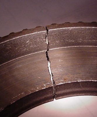
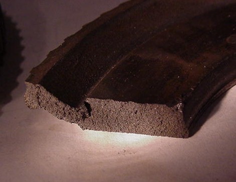
experience what the limitations are though.  Enclosed are a couple of
pictures of an actual Ford C6 bulkhead that was being prepared to have the
bolt circle drilled into it for use like the Powersport setup.   The builder
of the drive aborted the plan when I warned of the PM limitations.  Since
the part was then junk, I put it in a vice and hit it twice with moderate
hammer strikes and you can see the results.  It cracks something like cast
iron and has a very grainy, brittle structure.  Very strong when used in the
right way and I had a conversation with an engineer who knew the "right
way".  Best I can quickly translate is, you can't use it interchangably with
the steel alloys we normally use.  It is the opposite of 4130  which is
generally described as a "tough" steel.  It was his opinion that he would
never us a PM connecting rod in a high performance engine because of it's
limitations.

Tracy
Yes it certainly looks like a cast iron brittle fracture.
I don't think Everett tried it with torque isolation however.

Oh well I think we may be able to weld a large .25 inch thick
4130 washer on the back side of the bulkhead that contacts the
prop shaft. That should distribute the stress better. If that does not
pass the hammer test I think it would be not be all that hard to machine
one out of 4130. What weight hammer did you use?

Paul Lamar

The AirCraft Rotary Engine NewsLetter.              Powered by Linux.

http://home.earthlink.net/~rotaryeng/            http://www.linux.org