Leon Promet wrote:
Hi Paul,

You obviously got back OK!  Hope you enjoyed your short visit,  and that I
was of some assistance.  You seem quite chuffed with your new toy!!

As a wild card,  what about turning the manifold upside down and allow the
turbo to hang down.  That way,  the exhaust points towards the back of the
aircraft instead of forward,  and keeps it away from the engine mounts.  It
would also lower the centre of gravity of the engine.

Even if just the manifold was turned around and the turbo bolted in the
conventional config,  it would move the turbo towards the rear of the
aircraft, (but then there are standard manifold and waterpump clearance
hassles) and allow a lot more room to plumb the exhaust  dump pipe.  The
dump pipe needs to have a nice 90 degree bend on it to work best,  and
there is just not enough room between the mount you have in the picture,
 and the turbo flange.  Get a 3 inch mandrel bend and you will see what I
mean.

Just a thought,  as I don't have one sitting here on my desk right now to
fiddle with,  so I am doing kinematic inversions in my head!!  I'll
investigate further next week,  and take some of my own pix.  I now have
access to a digital camera (hooray),  so my scanning problems are over!.
(Everybody I know has a broken scanner!!)  Just have a play yourself,
 because if we have mounts across the minor axis of the engine,  the
exhaust egress will be in direct line with mounting bracket.

By turning the manifold upside down,  it lowers the turbo and points the
exhaust the other way.  All that then needs to be done is clock the oil
drain and the compressor housing around the correct orientation.  this also
means that it will be possible to have cool air flowing over and into the
compressor housing as in a car,  instead of hot air in the current config.
 Please have a careful think about it!!.

I've also had a hard think about bolting on the actual mounts to the bell
housing vs integral casting which would be a right proper bitch to set up
and machine.  The loads are no more severe than those experienced in a
rally car that continually jumps maybe 10 ft in the air and the suspension
bottoms.

However,  I think the smart thing is to have them as close in as possible
to the engine centre line as I don't like the idea of massive cantilevers!
If they are close together,  then the loads on the bolts are not nearly as
high.  If the turbo is turned upside down,  then there is also room to have
the mounting frame member pass between the turbo itself and the inlet
manifold.

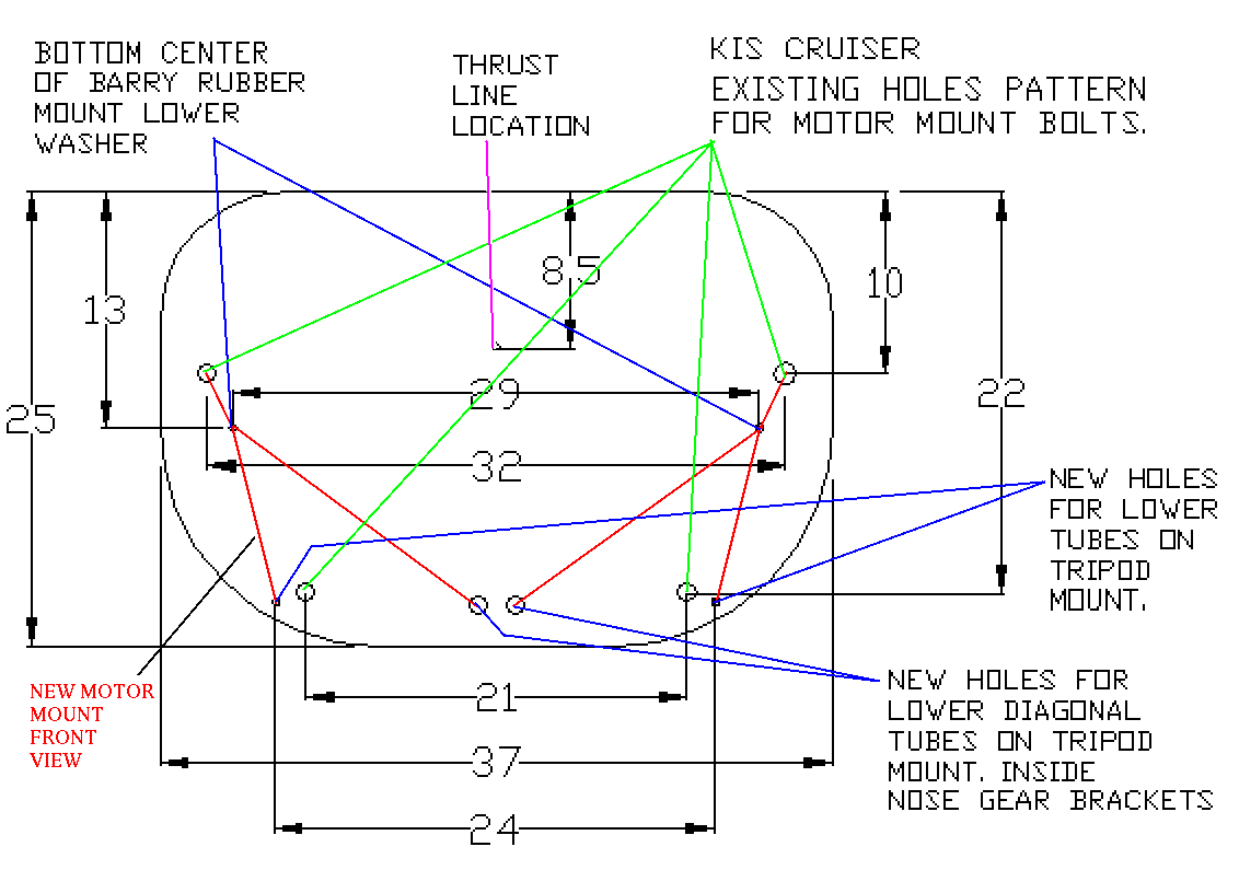
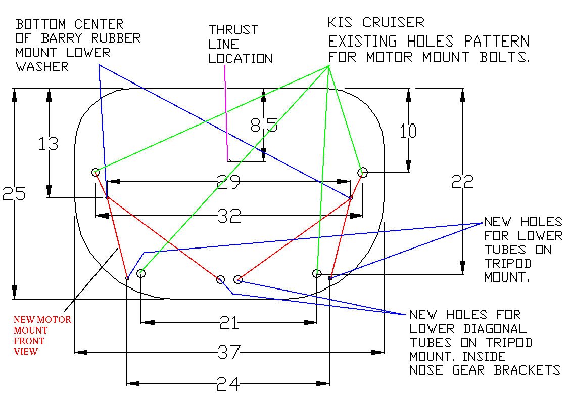
Can you please send me a firewall drawings with the dimensions and mounting
hardpoint locations on your Cruiser,  and can some of the other guys give
me some dimensions of their aircraft as well??  Say things like RVx's,  Ezs
and Velocitys please so that I can do some of my own mock ups??  Some side
and top elevations drawings would be really nice as well.

I need to fiddle and look at things.  I'll just get a piece of 3 ply and
make some prototypes out of exhaust tube to see exactly where everything
can/needs to sit.  This will also give me a physical idea of how much room
there is to fit radiators,  oil coolers etc.

I just know I'm going to be shot down in flames with this but here goes
anyway!!  Another flash of brilliance I had was to use those "chipmunk
cheek" cowls a la standard Lyc/Con engines.  Doing it this way,  it would
be possible to have the radiator/oil cooler arrangement split into 2
smaller units. I'm rather taken with those Lopresti cowls!!

I reason that the rotary engine block is not much bigger than the CRANKCASE
of the HOMFAE (Horizontally Opposed Mass Folly Aircraft Engine) stuff,  and
seeing there is all that lateral free space,  which is used to cool the
engine anyway,  why not stick a pair of radiators where the cylinders and
heads normally stick out in the breeze!  I was also looking at a quad cam
Subaru engine today,  and boy,  are they massively wide!!  Gimme a Wankel
 any day!!

Split rads and oil coolers worked really well with several Nova/Purvis
Eureka TCT (Totally Claustrophobic Transvestite) VW kit cars to which I
fitted rotaries in the '80s

http://community-2.webtv.net/ROAD-RAT3/CALIFORNIACOMPONENT/page3.html

The air for the 2 by 1300 Mazda rads, angled at 45 degrees very similar to
formula car set ups was taken from the top and side scoops.  2 small (half
width cut down RX7) oil coolers were placed up the front of the car and got
their air from the nose scoops on either side.  Doing it this way in an
aircraft,  you retain the Lyc/Con cowl config,  and then there is plenty of
room under the motor for a decent size muffler.  Heat soak can be minimised
by having a small thermostatically controlled computer cooling fan that
creates a nice breeze of cooling air over the muffler when the aircraft is
switched off until it is dead cold.

But this is all theory until I have some dimensions and can make a mock-up.
I'm sure that if anyone could,  you could come up with a really slick
aerodynamic solution! that would beat the pants off the Lopresti stuff!

Let me know what you think.  I'm bracing myself for the howls of derision,
 so everybody let their critical juices flow freely!

Best wishes and kindest regards,

Leon Promet
Thanks Leon for all your help. I will be talking about the trip for weeks
to come. Hanging the turbo upside down complicates the all important oil
drain back problem.

Paul Lamar

The AirCraft Rotary Engine NewsLetter.              Powered by Linux.

http://home.earthlink.net/~rotaryeng/            http://www.linux.org