Perry, Have you seen this web site?

Paul Lamar

http://www.gdsys.net/WWWmembers/unicorn/DUCTED_FAN/ducted_fan.htm

-- The UNICORN fan.

                 When I decided to design and build a ducted fan for the gyro
                 copter, I knew that I had to do better then existing fan designs to
                 make the gyro fly with 40hp. The first problem I ran into was the
                 airfoil for the blades. I was unable to match a propeller airfoil, as
                 recommended in the books, with the flow condition in the fan.
                 The answer I found in high performance industrial fans and the
                 confirmation in turbojet books. The airfoil should be very thin
                 and have a high camber. The major difference to a propeller, is
                 the much higher velocity increase over the blade. If using a prop
                 airfoil, it would be necessary to use two rotors with progressive
                 pitch.                                                                Secondly, the shroud has
                 to be long enough to prevent an outside vortex at no forward
                 speed. A one third diameter rule is a good start, however, the
                 power level is also to be considered. I found that the air on the
                 outside surface of the shroud is flowing forward from 10? behind
                 the inlet. I was glad that the shroud is 12? long. The 10? is 38% of
                 the 26? diameter. No book I read said anything about that.
                 Having a rough feeling about the required blade area, I realized
                 that I had to provide for more then three blades if I wanted
                 flexibility for experimenting. I settled on a maximum of 9 blades,
                 pitch ground adjustable. This gives me the option of using 3/6/9
                 blades depending on the engine size. Structurally, this design was
                 limited to 3700 RPM, which determined the total blade are.
                 Performance was not overwhelming, but it was sufficient to do
                 the flight testing and some learning, as far as this particular gyro
                 was concerned. With all the flight testing   done in 1999, I was
                 ready  to look into putting a bigger engine to the fan. The first
                 thing I did, was to convert the 40 hp setup to direct drive with
                 6500RPM max. This required, new blades for strength and power
                 match. What a disappointment. Thrust efficiency went down by
                 20%. and the noise level went up to a point where it  was
                 unbearable.                                   Conclusion? The essentially lower
                 total blade area used compared to the first, slow running
                 configuration resulted in a blade density low enough to cause a
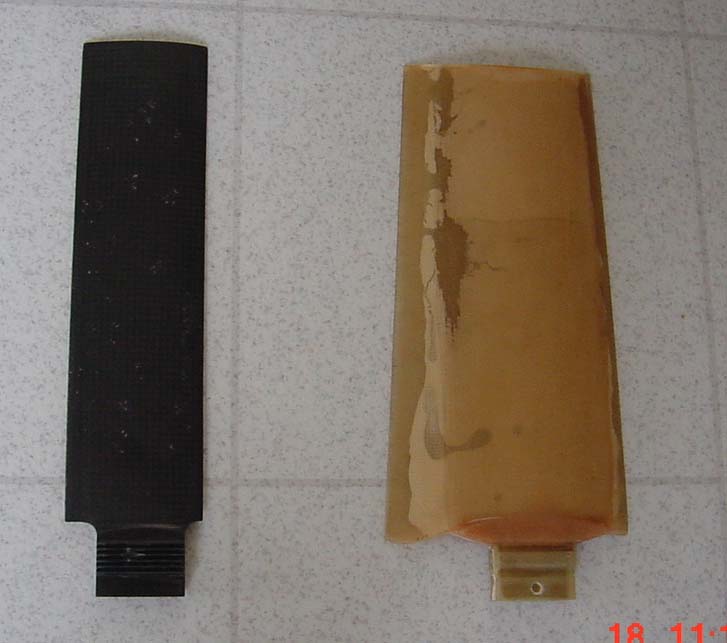
                 measurable change.                                 The blade shown on the
                                          right in the picture was
                                          used in the first, slow
                                          running configuration, it
                                          was molded fiberglass in
                                          epoxy. The one on the left
                                          is the new configuration in
                                          carbon fiber for up to
                                          7500RPM on a 8? hub.
                                          These blades do not have
                                          any twist, because of the
                                          low air speed the fan is
                                          used at.
                 Blade twist is a very peculiar issue in a fan. Because of the high
                 inherent velocity gradient over the fan diameter, a twist is not
                 applicable until really high forward airspeed is to be considered. I
                 do not know at this time what this speed may be, and I have not
                 been able to locate any flow field analysis answering the
                 questions. This issue is one of the first items to be investigated
                 with the new fan configuration. This investigation will also give
                 information on the airspeed at which a high speed shroud would
                 become an advantage. The only piece of data I have obtained
                 from my tests so far, is that at static running, the air flow on the
                 outside surface of the shroud is forward, as mentioned above.
                 With increasing airspeed, this point is moving forward until it
                 reaches the inlet lip. at this point, a high speed shroud becomes
                 essential.

                 The next configuration fan will be a 9-Blade rotor direct driven
                 by a ROTAX 583 engine. The shroud is the same as the one used
                 on the previous configuration.
                 The ultimate goal is a high speed fan competing with a same
                 power propeller in the same type of air plane.


The AirCraft Rotary Engine NewsLetter.              Powered by Linux.

http://home.earthlink.net/~rotaryeng/            http://www.linux.org