I'm am definitely not an expert on this subject, but I would like to share my
experience over the last 2 days during which I completely disassembled my 20B.

Removal of all the external components (if you have them) is self
explanatory.

Then, I removed the oil pan and oil pickup and then positioned the engine on
the floor with the oil pan mating surface down.  The next task was to loosen
the flywheel nut and front crankshaft nut which are both extremely tight.  To
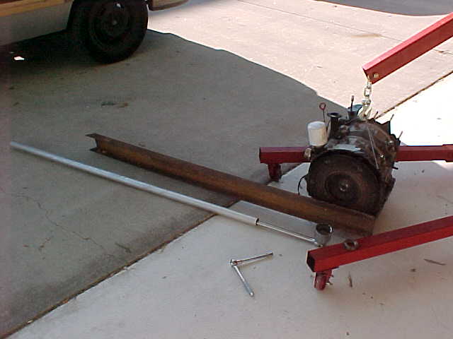
hold the E-Shaft from turning, I bolted a 4 foot long piece of 1.5 inch steel
angle to the flywheel using washers to space it up just off the ring gear.
Then using a 24" breaker bar and a 2 foot pipe extension I was able to break
the front crankshaft nut loose.  Only turn it enough to get it loose but
don't back it off yet.  Then I tried to break the flywheel nut loose the same
way but ended up breaking 2 breaker bars and then buckling the angle iron I
had bolted to the flywheel to hold it from rotating.  Finally I resorted to
heating the nut with a propane torch but this didn't help either.  After a
full day of trying various methods to break the flywheel nut free, I resorted
to chiseling the damn thing at one side until it rotated.  Luckily I had
already ordered a new flywheel nut from MazdaTrix.  I unbolted the flywheel
and removed it from the counterweight.  Then I slide two pieces of 1/8 inch
plate steel between the counterweight and stationary gear / rear seal.  Then
I put the bolts which previously held the flywheel to the counterweight back
in place and snugged them down such that the bolts bottomed out on the plate
steel thus putting the counterweight under tension (don't tighten too much or
you will damage the bolts or counterweight.  Rap on the side of the
counterweight with a hammer a few times and then retighten the bolts again
and rap it with a hammer once again.  This popped the counterweight loose
very easily.
Next, I positioned the engine with the front cover up and removed the front
cover, oil pump and drive gear, counter weight, thrust bearings, and front
stationary gear.  This is all self-explanatory as you do it.
Then I started to remove the tension bolts that run through the housings.
For this step, I got a good tip from Bob Darrah in the Austin, Texas area.
Since the tension bolts enter both ends of the engine, I again positioned it
with the oil pan mating surface down so I could get to both ends of the
engine at the same time.  There are three lengths of tension bolts:  Long,
Medium, and Short.  All the long and Medium tension bolts are installed from
the flywheel side, and all the short tension blots are installed from the
front cover side.  Remove all the Long and Short bolts but leave all the
medium length bolts in place.  If you remove a medium length bolt just put it
back and snug it down and move the next bolt.  Once all the tension bolts are
out except the medium length ones, position the engine on end with the front
cover side up.  Tape the threads on the end of the E-Shaft using electrical
tape for protection.  Tap on the end housing with a rubber dead blow hammer
to free it up and carefully lift it off.  Then tap the front rotor housing
and VERY carefully lift it so as not to spray apex seals, etc. across the
room as it comes off.  Next lift off the rotor making note of any oil control
rings/springs that may stay behind.
At this point, the E-shaft must be split to continue with disassembly.  This
requires a special tool which I had machined and then assembled.  (Cost ~
$80)  It is basically a puller that threads into a 18mm x 1.5  threaded hole
in the end of the E-Shaft.  Without this tool, this step seems like it would
be impossible, but with the tool it only took me 5 minutes to split the
shaft.  Now that I have a tool made, I would be happy to send it to anyone
who needs it as long as you send it back after your finished (or I can
provide you a drawing).  The puller basically screws into the E-shaft and
them goes up over the PROTECTED end of the E-Shaft thus providing a pulling
force parallel to the E-shaft when you hit the it with a hammer.  If you need
more info about this step of would like to borrow the puller just call me at
972-943-9050.
Once the E-Shaft is split, the rest of the engine unstacks very easily just
as in the previous steps.  When I got down to the last rotor housing, I found
it easier to simply lift the E-shaft out prior to lifting off the last end
plate and rotor housing.
I hope this helps someone!!!!  If not, just press "DELETE".
Good luck with your 20B projects and feel free to call me anytime.
Sincerely,

Don Mitchell
509 Tribal Rd.
Plano, Texas 75023
(972) 943-9050
MitchDCGS@aol.com
Velocity Standard Fixed Gear / 20B NA with Tracy's EC2 and RD-1B
Thanks Don. I have attached a picture I took when I disassembled my
engine. I feel your pain :-)

Paul Lamar

The AirCraft Rotary Engine NewsLetter.              Powered by Linux.

http://home.earthlink.net/~rotaryeng/            http://www.linux.org