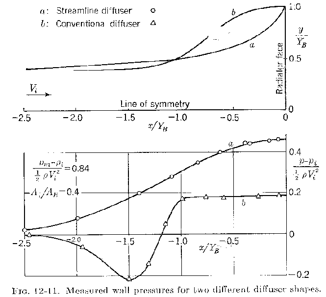
Some explanation is required for this chart.

Assume a perfectly square radiator 18 inches by 18 inches.

Starting at the top "a" is the actual shape of one of the
four walls of the duct or diffuser. "b" is the old
fashioned shape used as late as WW II on the P51,
Spitfire  and other liquid cooled aircraft.
Unfortunately it has also been widely used lately out of
the ignorance and lacking the knowledge of Kuchemann, Weber,
Hoerner and others :-)

The line of symmetry is a perpendicular line originating at
the center of the rad (9 inch by 9 inch) and continuing out
to the duct entrance.

Y sub b is the half the rad width and height dimension or
9 inch in this case.

The ratio y/Y sub b is the distance moving from the center
of the rad out toward the walls.

The ratio x/Y sub b is moving along the line of symmetry out
towards the entrance. For example -2 in this case would be
18 inches. The overall length of the duct shown is -2.5 X 9 or 22.5
inches. Obviously too long for our use but not to despair.
K&M have provided coordinates for other shorter duct lengths.
More on  that soon.

The ratio A sub i over A sub B is the ratio of the liner dimensions
of the intake over the dimensions of the rad. In this case it is
.4 so the dimensions of the opening are .4 times 18 inches or
or 7.2 inches by 7.2 inches. K&M have provided coordinates for
other ratios. This particular ratio or opening size is chosen
depending on the design speed of the duct. For example a larger
opening would be chosen for an air craft that climbed at 75 MPH
than one chosen for an aircraft that climbed at 100 MPH.

1/2 ro V^2 is dynamic pressure and is a function of air velocity.
ro is the air density constant  and for velocity measured in MPH it is
0.0052 at sea level and at standard temp and humidity.

At 100 MPH dynamic pressure is .0026 times velocity squared
or 26 pounds per square foot.

If you could recover 100% dynamic pressure the force on the rad
face would be 1.5 (18 inches) feet times 1.5 feet times 26 pounds or
58.5 pounds. This would be something like a WW I Spad rad mounted
ahead of the engine with a hole for the prop shaft.

Let's assume for the moment the rad is so thick and the fins so
close to together that no air can get through. The HP consumed
by this amount of drag at 100 MPH or 147 feet per second
is 147 times 58.5 pounds of drag or 8599 pound feet per second
or dividing by one HP 550 pound feet per second gives us
15.6 HP consumed by the rad alone at 100 MPH. At 200 MPH it would
be four times as great or 62.4 HP.  Fortunately this is not
WW I and we have learned to put our rads inside a streamlined
cowling with a proper duct. They still cause drag and consume
HP however. How little and still cool is the mystery and the trick.

Getting back to the chart. The pressure ratios given are
all relative to dynamic pressure so the pressure recovery of
the duct is extremely important to force air past the fins
and absorb heat from the coolant. These numbers represent the
overall efficiency of the duct. It is shown that a properly
designed K&M duct can recover twice the pressure that an old
fashioned WW II type duct can. That would probably be about
twice the airflow through the rad and roughly twice the cooling.
Maybe not exactly twice but a lot more for sure.

Paul Lamar

The AirCraft Rotary Engine NewsLetter.              Powered by Linux.

http://home.earthlink.net/~rotaryeng/            http://www.linux.org