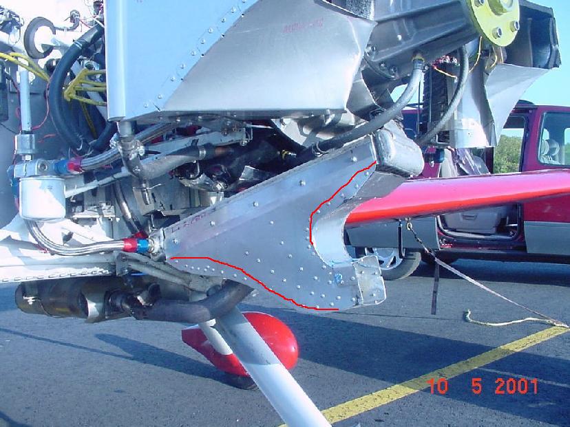
Here is another picture of Jerry Bass's oil cooler duct
better showing the guides or dividers. The original idea for
using these dividers was to provide uniform air flow
velocity through the heat exchanger.

Down through history these have been tried from time to time with
disappointing results. The reason is; a low energy boundary layer
is built up on the divider walls that displaces high velocity
air around the intake. Also skin friction on the various duct
walls is doubled or tripled further reducing the pressure developed
at the surface of the heat exchanger.

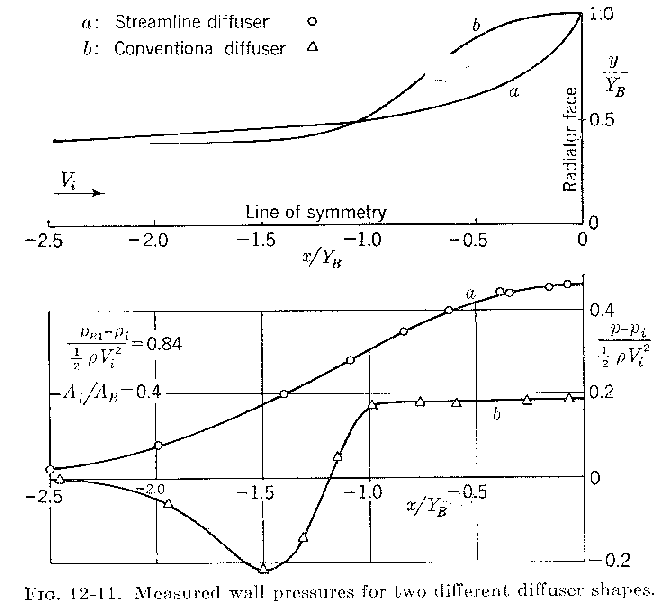
The best way to control the pressure distribution on the face
of the heat exchangers and optimize flow through the heat exchanger
is by changing the shape of the duct walls as shown by the red lines.
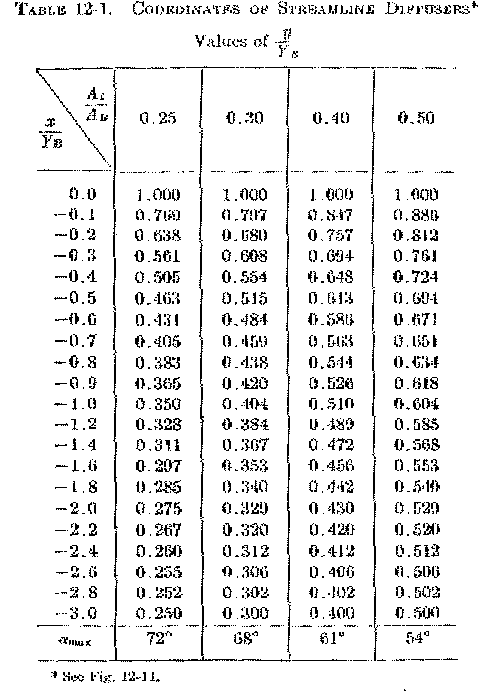
In fact Kuchemann and Weber developed coordinates as a function of
the linear length of the duct for an ideal duct shape. Given below.
You use these coordinates the same way you would plot an airfoil.

If you cannot for some reason make a duct using ideal coordinates
you can build an excellent duct with the trial an error method.

Obtain a throw away used furnace blower (contact any heating and air
conditioner contractor. I have three working ones) to provide air
velocity to the entrance of the duct and a wind speed meter to measure
a grid of coordinates on the back side of the heat exchanger
for uniform air flow velocity. A low cost water manometer can also be used
to measure the minute pressure distribution over the face of the heat
exchanger.

Paul Lamar

The AirCraft Rotary Engine NewsLetter.              Powered by Linux.

http://home.earthlink.net/~rotaryeng/            http://www.linux.org