Ian & Irene Beadle wrote:

I finally put a thermocouple on the outlet of my RV6A oil cooler.
The temperature drop across the cooler varies a bit with inlet temp.
but
is around 30 degrees C. The sump temperature gets up to 115C on climb at
1000 ft/min. Ambient 25 C. The water stays around 80 to 90. I haven't
done
any high power runs yet but indications are that this is one quick
aeroplane. I am swinging a 72"X81" propeller. 2.85 drive. RPM at start
of
ground run 5800.
I have sent some more information on the mixture indicator. The
components added to the input area are a clamp I found necessary to
protect
the IC.
Ian Beadle
beadles@webace.com.au
115 C is 239 F

Looks like Ian needs those teflon encapsulated silicon oil O-rings.

Paul Lamar
Ian & Irene Beadle wrote:
Paul. 115C (239 F) in the sump corresponds to 85C (185 F )oil feed to
engine from cooler.
Tracy reconds that max. at this point is 100C (212 F).
Ian.
85C (185 F) is still a bit high for cool oil out of the cooler IMHO. Are
you using
synthetic oil in the sump?  25C (75 F) ambient is a bit low for the desert
which it looks like. You do live in the outback don't you?

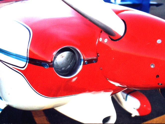
Is the blue scoop the oil cooler intake or air for the engine?

Paul Lamar
Ian & Irene Beadle wrote:
The blue scoop is experimental  air to the oil cooler. It is 3" in diameter.
Air to the engine is via a large NACA vent on the port side up top.(I copied
a fuel injected Lycoming RV6A.) I live in Perth Western Australia and fly
from a farm just north. It is winter here now. Temps get to the mid 30's in
the summer.
Ian
Mid 30's is more like it. About 95 F. That is when the steam hits the air stream
 :-)
Three inches is a bit small but it is in an ideal location. Perhaps four or five
inches diameter would be better.  It also needs about a 1/2 or a one inch radius
on the intake lip. That would make it near perfect with a bell shaped diffuser
where the hose feeds in. Ed Anderson had something like this at one time.
Worked pretty good but he never implemented the bell shaped diffuser part.

What do your cowl air outlets look like.

Paul Lamar
Paul,
I feel that most builders are undersizing their oil cooler inlet.  For
180 HP we seem to agree that a total cooling inlet area of 60 sq in to
80 sq in is needed and that 1/3 of this should be for the oil cooler;
this is suggested by both Fred Morino's engineering analysis and also
Ed Anderson's flying RV-6. That means that the oil cooler inlet would
need to be somewhere between 20 sq in and 26.5 sq in.  That would be a
5" to 6" round inlet.  I believe that Ed is now running an oil cooler
inlet of ~ 25 sq in and 2 radiator inlets of 25 sq in (correct me if I
am wrong there, Ed).  These numbers have been proven both with a
flying airplane and theoretically (Fred's engineering analysis).
Area for Round inlets:  (3" & 4" are not nearly enough)
   3"   = 7.07 sq in
   4"   = 12.56 sq in
   5"   = 19.63 sq in
   5.5" = 23.75 sq in
   6"   = 28.27 sq in

Didn't we decide some months ago that an oversize cooling inlet
probably wasn't really such a large drag producer?  Seems like
external diffussion would minimize the effects of being slightly too
large?

Ken Powell
What you say is true Ken but I still think if the inlet duct and cowl air outlet
are designed properly the hole can be smaller with less drag.
I have yet to see a bell shaped duct with a nice opening like this.

Paul Lamar

The AirCraft Rotary Engine NewsLetter.              Powered by Linux.
ACRE NL web site.
http://home.earthlink.net/~rotaryeng/            http://www.linux.org