Ken Powell wrote:
Tracy,
Please re-educate me.  I understand that the concept of dynamic
supercharging consists of 2 parts -intake pressure wave and exhaust to
intake crossover causing a pressure rise in the intake.
A. Intake pressure wave - one rotor chamber's intake pulse is used to
sort-of supercharge the intake to the other rotor.  This happens as the
intake port closes the air pressure in the intake tract rises.  This creates
a pressure wave which reverses direction and travels back up the intake
track to the opposite rotor at the speed of sound.
B. Exhaust / Intake pressure rise - As the exhaust port closes and the
intake port opens the high pressure exhaust will enter the intake tract
causing a pressure rise.  This also causes a pressure wave which reverses
direction and travels back up the intake track to the opposite rotor at the
speed of sound.
Based on this theory, on a peripheral port engine there would not be any
difference between a dynamic chamber and a plenum chamber - is this correct?
I am planning to build a chamber with a volume of ~ 2 liters.
Thanks,

Ken Powell
kenpowell@aristotle.net
I think you hit the nail right on the head there Ken. Well explained.
Therefor the dynamic chamber concept relies on that exhaust back pressure.

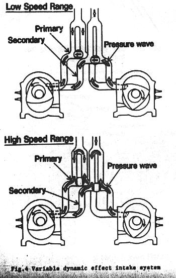
This diagram is from SAE paper 900036 New Technology Employed for the
Latest 13B-Rotary Engine. The HP curve is from an earlier paper that
mentioned the concept SAE 841017.

Paul Lamar
Tracy Crook wrote:

Poop!  Why do I get sucked into these debates!

 I see no reason why the dynamic chamber principle would be any different
with peripheral porting.  Ken, you correctly defined the basic principles
all the way through your message then totally distroyed the thing in your
conclusion.  Perhaps it may help if we define a plenum chamber.  I have
obviously failed miserably in my attempts to define a dynamic chamber.

As I understand it (others feel free to jump in here) a plenum chamber is a
reservoir of air (or fuel/air mixture) which is INTENTIONALLY DESIGNED to
damp out reflected waves, pulses, etc. reflected from closing intake ports
(or exhaust overlap).  It is the same function as a capacitor serves in an
electrical circuit.  These are used on engines (like V8s) where the
reflected waves from the various cylinders are as likely to hurt the other
intake cycles as they are to help.

Note that it is a fortunate happenstance that the timing is correct to help
all the time on a two rotor wankel engine.  A dynamic chamber on a V8 would
not work, nor would it work on a 20B three rotor (which is why Mazda didn't
use it there).  Note that there are no big chambers (plenums) in the intake
system illustrations.  Also note that the High & Low range labels are
backwards on the illustrations.

Is any of this making sense?

Tracy Crook
tcrook@rotaryaviation.com
www.rotaryaviation.com
No debate.

The dynamic chamber principle relies on the residual
exhaust pressure to give the inertia pulse an extra push
from the way I read it in Mazda papers SAE  841017 and SAE 900036.
Do you have those papers Tracy?
If this is ignored as would be the case with a normal tuned
intake manifold that little extra bit of energy is lost.

It appears to be highly dependent on the exact porting and manifold
configuration. That may be why Chuck so no improvement. It may or
my not work with peripheral ports.

It might shorten the length of the pipes by half but
pressure waves travel at the speed of sound so as such a dynamic
chamber is still tuned and subject to RPM effects just like a plenum system.
If not there would be no reason for Mazda to design the two stage
system shown in this reversed labeled diagram.

Then you still have to get fresh air into those pipes some how
and keep the pulse from going back out the throttle body. I suspect
it works better at partial throttle openings.  There
are no diodes in the throttle bodies :-) Might work even better
if there were pressure operated one way reed valves between the pipes
and the throttle bodies.

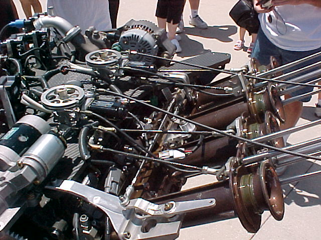
Mazda could have used this idea on the 4 rotor Leman engine but they choose not
to. The four rotor with peripheral ports and a traditional tuned intake
manifold generated a record, for an N.A. Mazda wankel engine, of 120 HP per
rotor at only 6000 RPM. That means a 13B would have 240 HP normally aspirated.

BTW The variable length of the runners had nothing to
do with how much HP it generated at 6000 RPM. These variable length
runners could have been replaced by fixed length runners and the HP
generated at 6000 RPM would be the same.

Paul Lamar

The AirCraft Rotary Engine NewsLetter.              Powered by Linux.
ACRE NL web site.
http://home.earthlink.net/~rotaryeng/            http://www.linux.org