> I think you hit the nail right on the head there Ken. Well explained.
Therefor the dynamic chamber concept relies on that exhaust back pressure.

This diagram is from SAE paper 900036 New Technology Employed for the
Latest 13B-Rotary Engine. The HP curve is from an earlier paper that
mentioned the concept SAE 841017.

Paul Lamar
Ed Anderson wrote:
 I am surprised at the diagrams showing Dynamic charging.  The low speed
range diagram shows shorter paths for dynamic charging than the high speed
range path.  I would have thought just the opposite.  My understanding that
Short tubes for high rpm (less time between port openings) were needed to
ensure the pulse from one rotor made it through the manifold in time to be
at the intake for the second rotor, and longer tubes for lower rpm (more
time between pulses).  Perhaps they are using multi bounce scheme ?.  The
two chart would seem to imply that dynamic charging is more significant than
intake manifold length tuning for rpm and power.  What am I missing.

Ed Anderson
Yes the diagrams are reverse labeled Ed. I forgot to mention that sorry.
Happens frequently in technically books and papers.

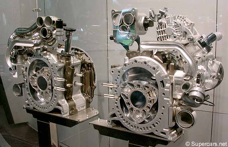
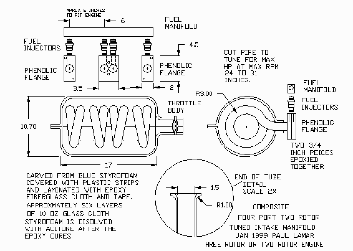
BTW Mazda is back to the intake manifold  drawing board on the RX8 because
of the side exhaust port. No overlap so no residual exhaust pressure to
affect the intake. As you can see they are using the classic real long pipes
to get torque down low with this naturally aspirated engine. I wonder when
they are going to discover the wrapped up intake manifolds? :-) Sure help
us out a bunch.

Paul Lamar

The AirCraft Rotary Engine NewsLetter.              Powered by Linux.
ACRE NL web site.
http://home.earthlink.net/~rotaryeng/            http://www.linux.org