Cliff Manzke wrote:

Rotaryites:

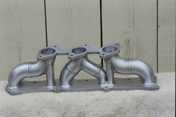
All the recent manifold discussions prompted me to spend some time on this manifold concept I've been thinking about.  Have a look at the attached Pro Engineer screen shots (JPEG files).  Nothing revolutionary, but perhaps something people might be interested in.  You may recall the 20B manifold I did for Al Gietzen (see attached pictures).  The big challenge with Al's manifold was making the transition from round tube to oval port within the confines of the tube bend.  The final solution was an expanding mandrel to form the oval shape from the inside of the tube.  The same tooling will work for the proposed 13B manifold, allowing a smooth transition from round to oval in a 1D bend (center line radius bend equal to the tube diameter).  There is nothing concrete about the manifold as designed so look at it as a concept only.  Tube size, runner length, total height, throttle bodies, fuel injector location, etc. etc. all need further design.......if anybody is interested.

The manifold as shown uses 1.50 X .065 inch tube for the primary runners and 2.00 X .065 inch tube for the secondaries.  1.875 or even 1.750 inch tube might be a better match for the secondaries, but again, this is just a concept.  The lower bends are all 1D CLR to keep things compact, while the upper bends could be larger (3.00 inch CLR shown) for a better fit around the rotor housings.  Runner length as shown is about 21 inches.  Total weight is 3.94 pounds (6061 aluminum, Pro/E calculation).

For those that might be interested you can email me directly.  And, think about the following:

1)  Injector location.  How many are using the housing mounted primary injectors?  I'm thinking four injectors is the way to go but is there a penalty for locating all four near the throttle body (or bodies) as Paul proposed?  A single fuel rail on the cold side of the engine sure sounds good.

2)  Throttle body location.  It seems like most are using a single throttle body on a common air box/plenum.  Using a throttle on each runner is an option, as is merging the primary and secondary runners for each rotor together and using dual throttles.  Making throttle valves is a option.  Using something like a TWM throttle body is another option.

3)  Runner length.  I'm probably opening a can of worms with this one but its obviously important.  The very quick calculations I've done suggest something between 18 and 22 inches for 6500 rpm and 85 F air temp.  How much real test data do we have on this one?

4)  Engine model.  As far as the 13B, are most using the '93 and later variant?

5)  Oil filler tube and cap.  This may have to be relocated as Paul has pointed out.  For those working on a custom oil pan you might thumb through the McMaster Carr catalogue for various sight tubes and windows.  Lots to choose from.

I'm quite busy with some other projects right now so it could be a month or two (or three) before I could deliver something, so in the meantime send me your thoughts and ideas so that I can stir them into the mix.

Paul:  There should be five pictures attached.  Let me know if they don't make it and I'll send them one at a time.

Cliff Manzke
Manzke Engineering
619-528-0588
cmanzke@home.com
That 20B is a work of art Cliff.

Paul Lamar

The AirCraft Rotary Engine NewsLetter.              Powered by Linux.
ACRE NL web site.
http://home.earthlink.net/~rotaryeng/            http://www.linux.org