There has certainly been a lot of work on this topic!  I still believe that a very reasonable solution would be to have a 90 degree lower intake manifold out of aluminum (or perhaps mild steel), similar to but much lighter and better configured than the stock manifold.  Then make the upper manifold in carbon fiber.

I think the best technique would be to build a "plug" out of foam or wax from the  lower  manifold to the throttle body.  Shaping blue foam into the upper 1/2 of the runners with a flat surface around/between each pair of tubes, then finishing the foam with micro filler would  allow the upper 1/2 of a mold to be pulled.  The flat surfaces would be a mating flange around each tube -- very strong!  The  contour could be  any shape necessary, such as winding around the front and back of the engine and around to a throttle body.  If you exceed 180 degrees, then a 2-piece mold would  be required on top - no big deal.

After the top mold has been pulled, a lower 1/2 plug would be built inside the upper mold, following its contours.  Then cast a lower mold off this combination.  Vacuum-bag in 2-3 layers of carbon fiber with hi-temp epoxy (overkill) into each mold half, pop 'em out and you have two parts to bond together to create a low-profile intake manifold.  The flanges could  be G10 phenolic (300 degrees).  Depending on the location, alignment and style  of the throttle body (and injectors), one additional box or mold might be needed for the dynamic chamber and its flange.  After it is done, you have a mold from which dozens of manifolds could be produced.  Probably would weigh around 1 lb.

Depending on the precise length needed, options might  include wrapping the tube so a relatively small throttle body was on top of the crankcase, or a longer length with the T.B. dropped off the side.

I'm happy to work on this (upper) end of such a project, but  need a lower intake manifold  to start with and a reasonably close design.  Cutting  down  the  stock manifold still results in the center tubes too close together, so I'm still evaluating my options for a new version.  Seems like it  would be much better to run the front two tubes close together, and also the rear tubes together.  This means the lower intake manifold needs to start out in the right  direction.  The upper manifold would  also be a lot simpler this way -- just  two  pairs of tubes running independently between the flanges.

So the bottom line is, if there are few or no restrictions on the shape of the  upper manifold, what is the most ideal design?  I'm pretty good  with composites and molds, but not a welder (no Henrob, yet).  Anyone interested in this scenario?

Scott Gettings
Yes. I am looking at making a pattern for just the bottom 90 degrees.
If I could only figure out how to get the cores in the mold.

I now understand core boxes, core prints, drags and copes.
I still don't fully understand curved parting lines.
I need to take a trip up to the foundry and have a look around.
OK, I'll wait on Paul.  Are you planning a NA and turbo version?  I know that your installation is a turbo.  Obviously more complex than a NA manifold.  For the NA, we'll still need at least one drawing of an ideal upper manifold as the mold will be non-trivial.

I was about ready to go with Tracy's flange, some standard 90 bends, and make a secondary flange to complete the lower manifold.  If Paul is working on another solution, I'll just wait.

Scott Gettings
Its a turbo version. The new plan E is a 180 degree version.
I got no commitments from my friend to make the patterns yet Scott.
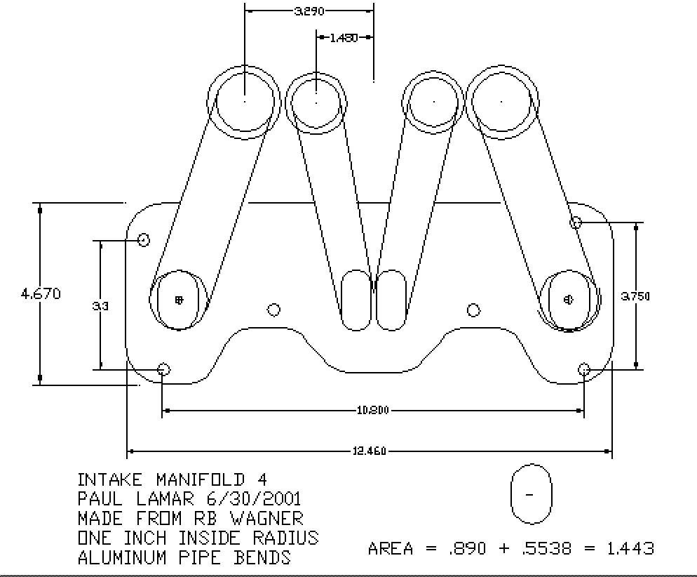
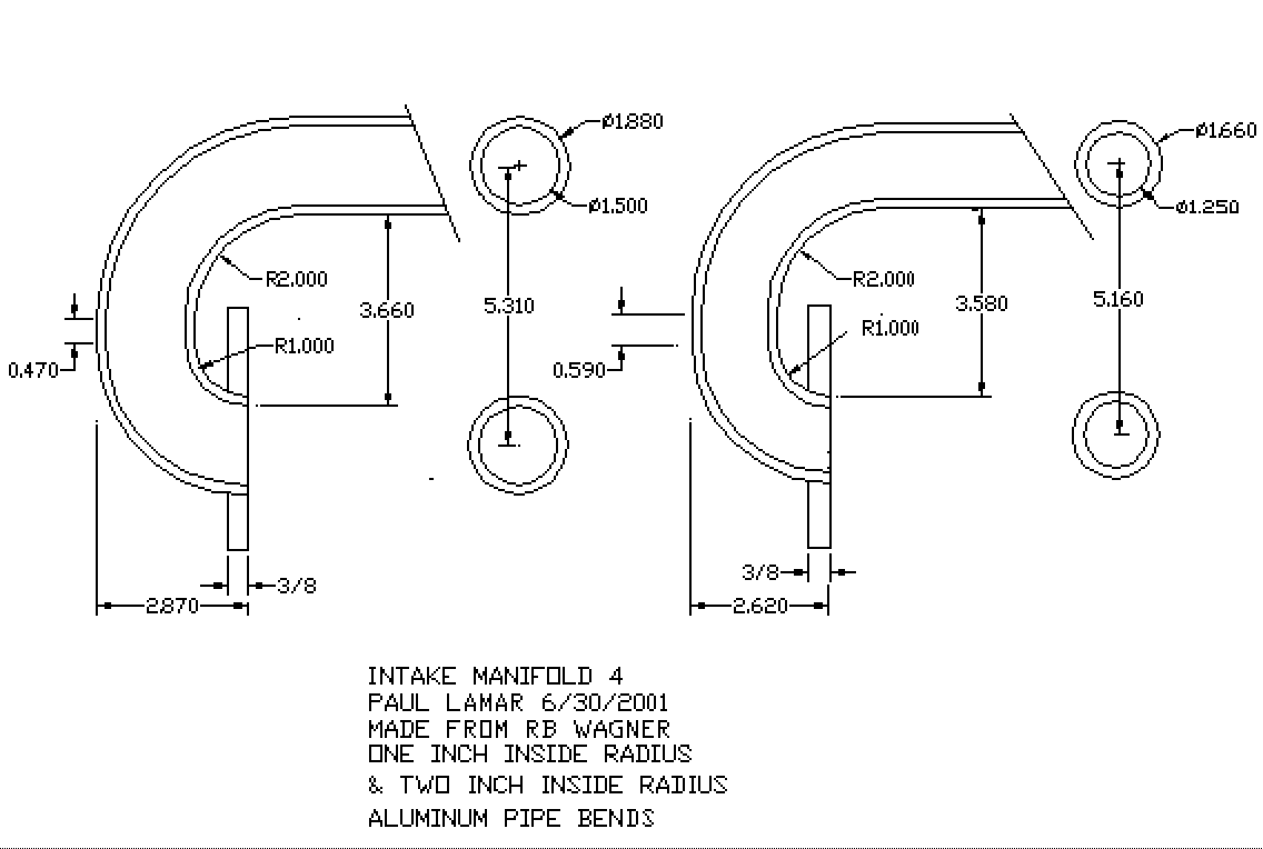
So I would not wait. You can fab one from RB Wagner bends for
about the same cost. Just a lot more work with tig welding required.
Sketches below.

Paul Lamar

The AirCraft Rotary Engine NewsLetter.              Powered by Linux.
ACRE NL web site.
http://home.earthlink.net/~rotaryeng/            http://www.linux.org