Lonnie Wood wrote:
Lonnie wrote>
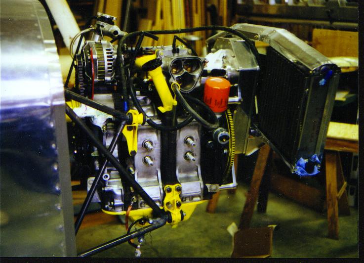
Attached is a picture of my oil filler cut and angled over to make
room
for
the intake.
Lonnie Wood
Mark wrote>

That is a very clean looking engine mount installation. Are those
modified
stock mount brackets? How is this braced for side loads?
Mark Wrathall
Good call Mark. I had not noticed that.
I think you need some diagonals Lonnie. Perhaps a bent tube
down and under the pan with diagonals from the center of that.
The tops are more of a problem.

Paul Lamar
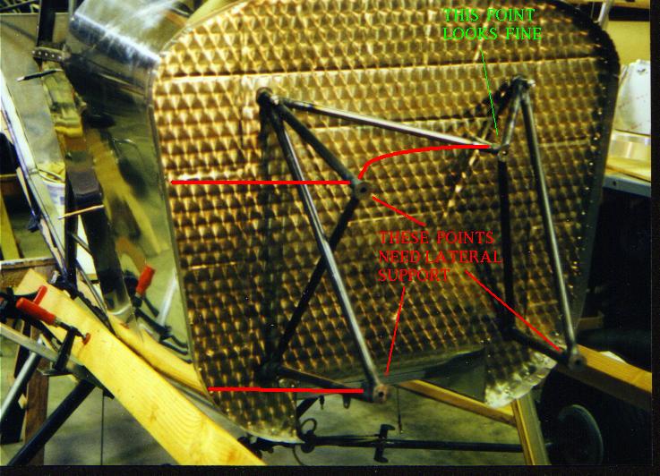
Here is a picture of the mount that shows the top diagonal. I made a scale
model of this with scale engine as Paul recommended. It seems very stiff in
all directions. If you look at real airplane engine mounts many are made
this way with one top diagonal. Any specific recommendations on making it
stiffer are welcome. Glad you guys are watching.
The trick to remember is; each rubber mount point in space must be supported
by at least three tubes. If you glue the engine to your model it
will fool you as the engine acts like a tube in the model but
in the  full scale mount there are rubber bushings at those points.
For my model I actually built small scale rubber bushings.

The upper left mount looks fine.

There are two possibilities for fixing the upper right mounting
point. One is a bent tube around the back of the engine from
the other side and two; a simple diagonal back to the fire
wall. I recommend #2. Number 1 does not look too practical.

The lower tubes are easy to fix with diagonals over to the
edges of the firewall.

What kind of airplane is this Lonnie? I am kind of surprised
the motor mount hard points are in the middle of the firewall
like that. Most are out near the edges of the firewall near
the skin. Is the skin surrounding the firewall structural?

Paul Lamar

The AirCraft Rotary Engine NewsLetter.              Powered by Linux.
ACRE NL web site.
http://home.earthlink.net/~rotaryeng/            http://www.linux.org