Wrathall Mark wrote:
Paul, from http://www.epi-eng.com/PSRU_Tech.htm...

Whirl mode is a divergent oscillation of the engine and mount about an axis
parallel with the static thrustline.

It occurs because of the positive feedback loop which occurs when a large,
sudden gyroscopic moment is applied to an engine mount structure which is
insufficiently STIFF (as differentiated from STRONG).

The feedback loop occurs because a gyroscopic moment, which is produced by a
pitch or yaw velocity, is applied in a plane which is 90? to the angular
velocity (pitch or yaw) which caused it. If the excitation mode couples with
an engine mount resonant frequency, the prop-end of the powerplant can begin
to whirl around an axis parallel to the static prop centerline, describing a
cone of ever-increasing base diameter.

For example, suppose that an aircraft, which has an engine mounting
structure with insufficient STIFFNESS, encounters a violent vertical gust
which causes it to pitch-up rapidly. If the prop rotation is clockwise, the
upward pitch excursion produces a prop gyro-moment which tries to deflect
the engine mount structure to the right. If the mount is sufficiently
flexible, it would deflect rapidly to the right (yaw), which would generate
a downward gyroscopic moment on the engine mount. The flexible mount
deflects downward (pitch), causing a yaw-left moment. That
90-degrees-out-of-phase excitation continues, and if these excitations and
deflections occur at some harmonic of the natural frequency of the
engine/mount system, the deflections can develop into a whirling deflection
of the engine structure of increasing amplitude until something breaks.

Early in the days of turboprop-powered aircraft, there were several inflight
breakups caused by engine nacelle departure from the aircraft because of
whirl mode. It happened because the engines were much lighter and much
longer than the radial engines of comparable (or less) power. The longer
mounting structures, which were designed to carry the g-loads appropriate
for the powerplant weight, were relatively more flexible than those designed
to carry the heavier and shorter radial engines.

A similar scenario is possible with a high-powered, relatively light V8. The
engine mount sufficient to bear the g-loads might not have sufficient
stiffness to prevent whirl. It is less likely to occur with the low
mass-moment-of-inertia (MMOI) composite props commonly found on experimental
aircraft, but a higher probability exists with a large MMOI metal prop. It
is a subject which demands analysis in each installation.

Have you taken this into account with the design of your mounts?
Mark Wrathall
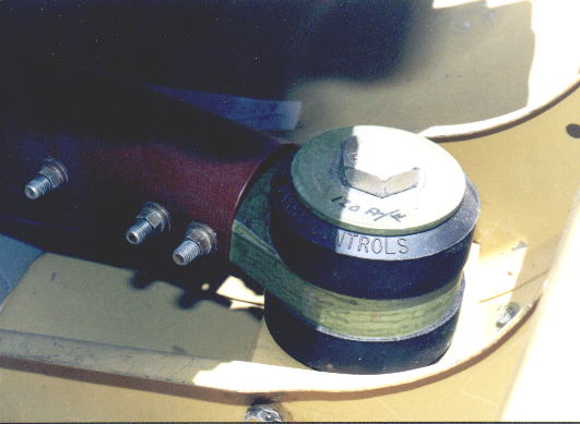
No but I will certainly watch for it. So far nobody has reported this
on the Questair Venture with up to 550 HP dual turbocharged TIO-550
and metal constant speed props. As I said my mount is near identical
with exactly the same brand of rubber bushings but only one size
smaller. One thing we have going for us over the traditional bed
or Lycoming dynafocal mount is our bushings are much further apart
at 29 inches center to center. Here is a picture of the Questair
mount.

BTW this web site uses the well known FUD method of marketing.

"It is a subject which demands analysis in each installation."

Fear Uncertainty and Doubt. IBM was famous for it back in the
1960's and 70's. Any obscure technical thing you can come up with
that is not well known and difficult to calculate works fine :-)

Paul Lamar

The AirCraft Rotary Engine NewsLetter.              Powered by Linux.
ACRE NL web site.
http://home.earthlink.net/~rotaryeng/            http://www.linux.org