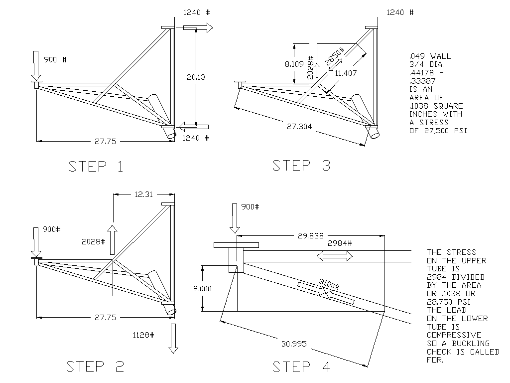
Step 1 gets the basic reactions on the firewall.
It is assumed the engine weighs 300 pounds with prop, psru,
starter, alternator, intake manifold and exhaust manifold. There
is a six G pull up. Total load is six times 300 or 1800 pounds.
Each side of the mount therefore takes 900 pounds.
It is actually a little less than this as the rubber bushings
in this design are slightly ahead of the engine CG so the rear
mount takes some of this load. Also the tube bracing the
RV4 landing gear socket tubes is ignored in this case.
When the six G landing case is explored it will then come into play.

Step 2 gets the load on the joint between the down tube and the
truss. The arrow at the firewall points in the wrong direction.
I will fix that next time. Once we have that load we can calculate
the tension load in the down tube. This is a grammar school math
see saw problem.

Step 3 uses the graphical technique to calculate the load in the
down tube. A line is drawn proportional to the load and a right
triangle is drawn to intersect the tube. The length of the last
diagonal leg of the triangle is proportional to the tension load
in the tube. In this case the proportions are four to one.
The area of a 3/4 inch diameter tube with an .049 wall is .1028
square inches so the tensile stress in the tube is 27,500 psi.
Well within the capabilities of 4130 tubing.

Step 4 is a blow up of the intersection of the tubes at the rubber
bushing gizmo. Here loads in both tubes are calculated. The line lengths
are ten times the load ignoring the decimal point. The upper
tube is no problem as that is in tension. The lower tube is in
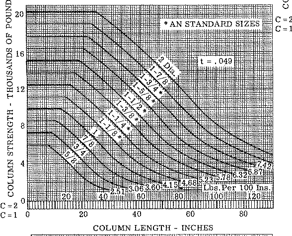
compression so lateral buckling rears its ugly head. We need to look in the
buckling chart and see if that 27 inch long tube can take 3100
pounds. Looking in the chart the C2 scale is for welded ends
and the C1 scale is for non welded ends. We have welded ends
but 3/4 OD looks a bit marginal even for the welded end case
so I suggest going up to 7/8 inch OD  0.049 wall
for this tube. The buckling chart is from the bible of aircraft
structural design I.E. Analysis of Flight Vehicle Structures
by E.F Bruhn Tri State Offset Company.

I got more to go on this as I need to calculate what happens
when the RV4 is dropped in at six G's. BTW I think this is
a bit conservative as I recall Vance said KIS and the FAA Fars
use or recommend 4.5 G's for landing loads.

The remaining loads for this case I will leave as an exercise for the
student. I always wanted to be a college professor and be able to
say that :-)

Paul Lamar

The AirCraft Rotary Engine NewsLetter.              Powered by Linux.
ACRE NL web site.
http://home.earthlink.net/~rotaryeng/            http://www.linux.org