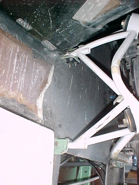
"Perry J. Mick" wrote:
Paul:

I think I'm going with your new design when I redo my
engine mount, because I  won't have to modify the
airframe at all, and I think the engine won't move as
much with this mount because the rubber is closer to
the engine.

These drawings show the correct Rutan thrustline.
I had to move the left mount slightly forward otherwise
it would interfere with the rear oil port on the engine.
The one on the right needs to go rearward to avoid
the exhaust, so the two are about 1" apart longitudinally.

There were two rotary powered airplanes at Tillamook
today, Ken Welter was arriving at the museum as I
was leaving.
What are you going to hang the duct on?
The engine, same as now.
Have you run across Jim Wilhaer and his rotary powered Murphy Rebel?
He recently moved to the Portland area?
Not yet, but I've recently met Mike McGee, Aurora, and Lonnie Wood,
Coos Bay.  I think there's an ultralight flying around MMV with the
German  Wankel in it.

What do you think of how I tied the front rubber mount to the
1x1.5 inch rectangular tubes?  It's in the top view.

--
Perry Mick
Duckt N7XR
http://www.ductedfan.com
Last time I talked to the guy with the German wankel in an Ultra Bibe
he sent it back to Germany for repair and never saw it again. That was
at the Arlington flyin this year.

Ops I forgot to send that one. Here it is.
Hey that's pretty simple. That will work for a lot of motor mount designs.
For those that may not be aware of what Perry is doing here
is he is taking Tracy's idea one step further and expanding the
antifoaming 1/4 inch thick plate forward (in this case) to make a
front motor mount bracket. Simple! Good idea Perry. Brace that biped
or use a piece of rectangular tubing between the upright rectangulars
to take the front mount load in bending. You might have to extend the
anti-foaming plate a bit further but that should be no problem
as the main rubber bushings are pretty close to the CG of engine
prop and duct.

Paul Lamar
Paul,

I like everything about this engine mount design except for one thing. The
mounting bolts are in single shear. I realize that the primary loading will
be due to G loading during hard landings and maneuvering, but in the case of
a crash and frontal impact the bolt will have to take a tremendous bending
load, which will also be introduced into the mount itself. (much easier to
peel something apart than pull or shear it) We should try to come up with a
way to put the bolt in double shear. This would insure that the bolt only
sees shear or tension loads. Also where the channel is mounted to the
firewall hardpoints, the bracketry should be designed to ensure that the
bolts only see tension and shear loads. Bending must be transferred through
the bracket to the longerons. I was planning on doing this by welding either
channel or angle to the Tubing and bolting this to the longerons in place of
the aluminum angle that is currently used. This could make for a
self-jigging type of construction at the rear of the plane if done properly.
This way there is no bolted connection to worry about at the firewall
hardpoints.

Even though the max load will be due to hard landings etc. repetitive cyclic
bending loads due to gyroscopic, thrust, and whirl forces should not be
discounted. All of these will result in bending loads in the bolts which go
through the rubber grommet at the engine. If there is any thread exposed you
have a good recipe for fatigue failure. Only the round shank of the bolt
should see any shear loading. Unless you have a precision hole that is at
least 1 bolt diameter thick, you are probably going to get some bending in
the threads of the bolt in a compliant rubber connection. If you put the
bolt in double shear, this problem is eliminated and you can safely use a
smaller/ lighter bolt. Or possibly drill out a larger one to save some
weight. More likely than not you will be OK as is, because the bolt you will
be using is so large. But, I thought I would add my $.02 . As soon as I can
get to it, I will post a model of what I have in mind. The idea of tying the
engine mount structure directly to the main gear is the only way to go.

Monty
That Barry rubber bushing bolt  is a half inch in diameter so I am not
worried about that. It also clamps a steel spacer that is about 3/4
inch in diameter.

All the stock Long EZ motor mount bolts are in single shear and they are bolted
to 1/8 wall, one by one inch, aluminum angle!!! The bolts themselves look like 1/4 inch
but they could be as large as 5/16 the :-) Granted there are two per mount.
Holes are drilled in 1/2 inch diameter thick wall steel tubing welded to the
motor mount proper. The aluminum angles themselves have been known
to fatigue and crack. Klause had to route out his and replace them with bent
4130 steel sheet.

In our design the gizmo holding the the 1/2 inch Barry rubber bushing bolt is
probably ten times stronger.

Paul Lamar

The AirCraft Rotary Engine NewsLetter.              Powered by Linux.
ACRE NL web site.
http://home.earthlink.net/~rotaryeng/            http://www.linux.org